Grinding design guide: tolerances, stock allowance and wheel rules
Learn when to specify grinding, how much stock to leave, how to design features for wheel clearance, and how to prevent heat damage.
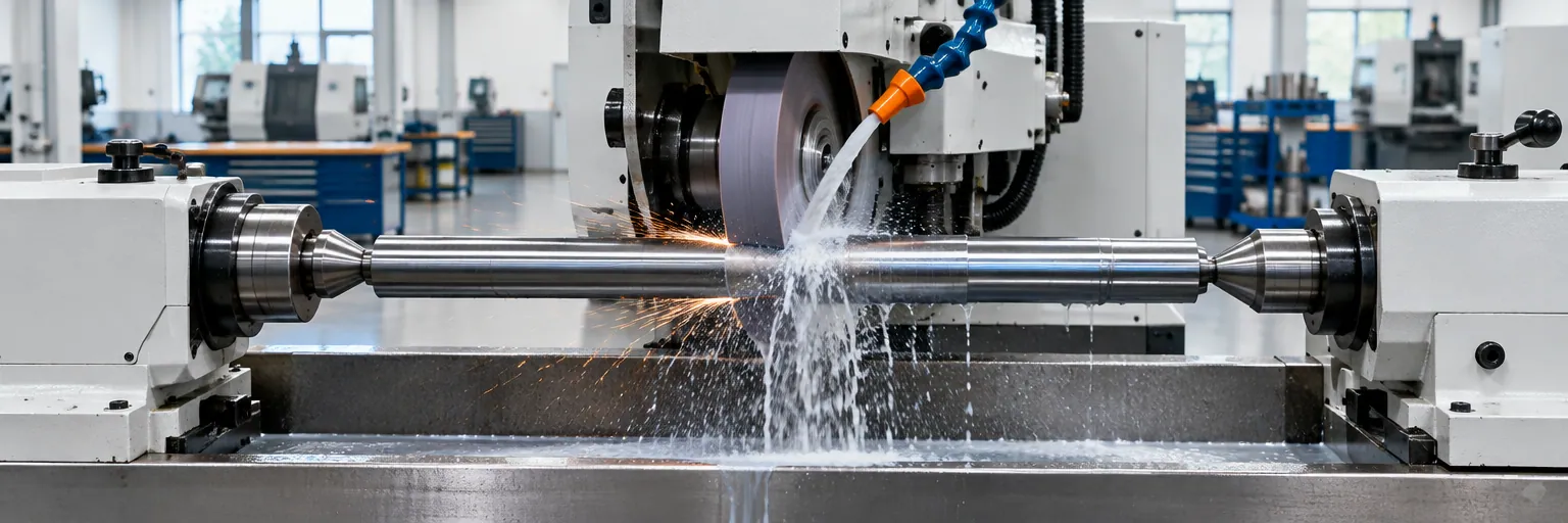
Grinding is an abrasive machining process that uses a high-speed bonded abrasive wheel to remove tiny chips. Engineers specify it to finish hard materials and hold tight tolerances or fine surface finishes on flat, cylindrical, and contoured parts. Because every abrasive grain cuts with a negative rake, grinding takes very light passes and generates significant heat that coolant must carry away.
What grinding is and when to use it
Grinding runs on surface, cylindrical, or tool and cutter grinding machines. You can also perform basic grinding on an engine lathe using a tool post grinder at low work speeds and shallow cuts under 0.002 in, provided the lathe ways are covered with paper or a water pan to protect them from abrasive dust.
Use grinding as a finishing operation after milling, turning, and heat treatment. Specify it when:
- The material is too hard to cut with a standard cutting edge, such as hardened tool steel (rated excellent for grinding) or fully sintered zirconia, which requires diamond grinding.
- The required dimensional tolerance or surface finish goes beyond what milling or turning can hold.
- Surfaces must be flat, round, or parallel to within a few micrometers.
Typical ground parts include hardened shafts, bearing seats, gauge blocks, tool and die faces, and precision fixture plates. Soda-lime and borosilicate glass are also rated good for grinding with abrasives and coolant to finish edges and holes, though borosilicate wears tooling faster. If glass will be tempered or heat-strengthened, do all cutting, drilling, and edge grinding in the annealed state first; grinding tempered glass releases locked-in surface stress and shatters the part.
Designing parts for grinding
Leave a small stock allowance during rough machining for the grinder to remove. According to published Army machining guidance, leave up to 1/32 in on large machine-steel parts when using a modern grinder in good condition, and generally no more than 1/64 in on small parts. Always confirm exact stock allowances with your shop.
A rotating wheel must physically reach every surface you mark for grinding:
- Internal corners will take on the edge radius of the wheel.
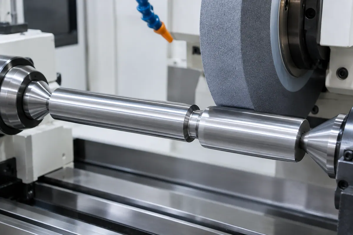
- Ground shafts stepping up to a shoulder need an undercut or relief groove so the wheel edge does not interfere.
- Deep bores require internal grinding with a small wheel on a spindle quill. Design bores as large and short as practical so the machinist can fit the largest, stiffest quill possible; small quills spring away from the cut and produce unwanted tapers. The hole design must also allow the wheel to run out the end of the bore by one half to two thirds of its face width on each stroke, or quill spring will leave a bell-mouthed hole.
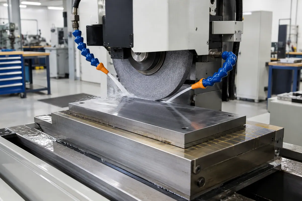
- Thin parts warp easily as grinding alters their internal stress state, and standard magnetic chucks on surface grinders only hold ferrous metals.
Surface finish and drawing callouts
In ordinary production, grinding produces an average surface roughness from 0.1 to 1.6 micrometers Ra (4 to 63 microinches Ra), going from fine to ordinary grinding. Finer or rougher finishes are reached less often and depend on the material, wheel, and machine settings. Because reference handbooks and training manuals do not set guaranteed shop tolerances, confirm specific geometric and dimensional capability limits directly with your supplier.
Keep these rules in mind when detailing drawings for ground parts:
- Specify surface lay on sealing and bearing surfaces, because a ground finish is directional.
- On linear motion shafts used with ball bushings, call out a straightness tolerance alongside the diameter tolerance. A shaft that is not straight causes bushings to bind, run noisily, and wear out early.
- On conical or tapered features, note that the shop must keep the workpiece axis and wheel axis (or internal quill axis) at the exact same height to generate the true taper angle.
Wheel selection and operating parameters
Grinding wheels are specified by abrasive type, grain size, grade (bond hardness), structure (grain spacing), and bond material. Pick the abrasive based on the tensile strength of the workpiece:
- Aluminum oxide is tough and resists fracturing, making it right for high-tensile materials: carbon steel, alloy steel, high-speed steel, annealed malleable iron, wrought iron, and hard bronze.
- Silicon carbide is used for gray and chilled cast iron, brass, soft bronze, aluminum, copper, stone, rubber, and cemented carbides.
- Diamond is required for fully sintered zirconia.
Match the grain, grade, structure, and bond to the job:
- Grain size: Use coarser grains for soft, ductile materials and heavy stock removal; use finer grains for fine finishes.
- Grade: Use a softer grade for harder materials and larger contact arcs (like surface or internal grinding) so the bond releases dulled grains before the wheel glazes. Use a harder grade for small wheels and high work speeds.
- Structure: Choose an open structure for surface grinding and soft materials, and a medium structure for cylindrical and tool grinding.
- Bond: Vitrified bonds serve up to 6,500 sfm (1,981 m/min). Above 6,500 sfm, or on thin cutoff wheels and high-finish work, use resinoid, shellac, or rubber bonds (resinoid snagging wheels typically run at 9,500 sfm, or 2,896 m/min). Very large solid wheels use a silicate bond.
In precision cylindrical and surface grinding, roughing cuts are generally 0.001 to 0.003 in deep with a traverse feed of about three quarters of the wheel width. Finishing cuts are 0.0005 down to 0.00005 in deep with a traverse of one third to one half of the wheel width (halve the table traverse on surface grinders when using wheels under 1 in wide). Workpiece surface speeds typically run 50 to 80 sfm on surface grinders and 60 to 100 sfm (18.3 to 30.5 m/min) on cylindrical and internal grinders, dropping to 20 to 30 sfm (6.1 to 9.1 m/min) for heavy roughing and rising up to 200 sfm (61 m/min) for aluminum or 150 to 400 sfm on cast iron pistons. Typical cylindrical work speeds are 35 to 40 sfm on crankshaft pins, 50 to 55 sfm (15.2 to 16.8 m/min) on steel shafts, and 80 to 85 sfm (24.4 to 25.9 m/min) on hard steel rolls.
Tool and cutter regrinding
Milling cutters cannot be sharpened offhand; they require a tool and cutter grinder with a medium-structure wheel. When sharpening plain milling cutters, grind the primary clearance angle of the land to 3 to 5 degrees for hard materials and about 10 degrees for soft materials like aluminum. For cutters under 3 in diameter, increase this to 7 degrees for hard materials and 12 degrees for soft materials. Keep the land 1/32 to 1/16 in wide with a secondary clearance angle of 20 to 30 degrees (usually 30 degrees), and hone the edges with a fine oilstone afterward.
End and side teeth take about 2 degrees of clearance, with the face ground 0.001 to 0.002 in concave toward the center. Too much clearance leaves a weak edge that dulls quickly; too little causes the cutter to rub and overheat.
On form-relieved milling cutters, grind only the tooth face using a medium (36 to 60 grain) cup or dish wheel, never the land, or you will destroy the cutter profile. Maintain the original positive rake angle (commonly 10 to 15 degrees, most often 12 degrees) and set the depth of cut by rotating the cutter rather than shifting it parallel to the wheel spindle.
What to watch out for: heat, setup, and safety
Heat is the primary failure mode in grinding. Taking too heavy a cut, letting the wheel dwell in one spot, or running a glazed wheel burns the metal, tempers hardened steel, and leaves tensile residual stresses and surface cracks. Flood the contact point with coolant whenever practical. Soluble oil in water or a solution of 1/4 lb of sodium carbonate per gallon of water works for most metals, while plain water works well for aluminum.
Good machine setup prevents geometric errors:
- Mount grinders rigidly on cushioning material with aligning shims, and check plumb every few months to prevent vibration and irregular surfaces.
- For cylindrical grinding between centers, use a dead center in the tailstock to eliminate spindle bearing wear error, check center alignment, drive the work with a lathe dog, and rotate the work and wheel in opposite directions at the contact point.
- Read the sparks during cutting: spark volume indicates cut depth, and uneven sparks show that the work or wheel is out of round.
Grinding wheels can shatter if mishandled or oversped:
- Ring-test every wheel before mounting by tapping it with a light non-metallic handle or wooden mallet; discard any wheel that does not give a clear ring.
- Mount wheels between relieved flanges (about one third the wheel diameter) with paper blotters no more than 0.025 in thick and a spindle hole fit within 0.002 in.
- Never exceed the wheel's tagged maximum safe speed. Check spindle speed with a tachometer and compute surface speed in sfm as diameter in inches times RPM divided by 12. Raising wheel speed makes a soft wheel act harder; lowering it makes a hard wheel act softer.
- True and dress every wheel immediately after mounting at or slightly below operating speed, feeding a diamond dresser about 0.001 in per pass (on a lathe tool post grinder, set the diamond at center height angled 10 to 15 degrees toward rotation, taking up to 0.002 in per cut and 0.0005 in final).
- On bench grinders, set the tool rest 1/16 to 1/8 in from the wheel. On wheel-type portable grinders, confirm the wheel's rated speed exceeds the tool's speed, keep the guard on, keep the wheel moving with light pressure, and grind only on the wheel face, never the side.
Design rules at a glance
| Rule | Value | Note | Source |
|---|---|---|---|
| Typical surface roughness (Ra) | 0.1 to 1.6 µm (4 to 63 µin) | Average production range from fine to ordinary grinding. | [4] |
| Stock allowance (large machine-steel parts) | Up to 1/32 in | Published guidance for a modern grinder in good condition; confirm with shop. | [2] |
| Stock allowance (small parts) | At most 1/64 in | General allowance for small machined parts before finish grinding. | [2] |
| Roughing depth of cut | 0.001 to 0.003 in | Precision cylindrical and surface grinding, depending on machine and hardness. | [2] |
| Finishing depth of cut | 0.00005 to 0.0005 in | Light passes for final size and finish. | [2] |
| Tool post grinder max cut depth | 0.002 in | For grinding on a lathe at 60 to 100 sfm work speed with ways covered. | [2] |
| Traverse per pass or revolution | 3/4 wheel width (rough); 1/3 to 1/2 (finish) | Halve table traverse in surface grinding if wheel width is under 1 in. | [2] |
| Internal grinding wheel runout | 1/2 to 2/3 of wheel width | Distance wheel should exit the bore at each stroke to prevent bell-mouthing. | [2] |
| Max wheel speed (vitrified bond) | 6,500 sfm (1,981 m/min) | Use resinoid, shellac, or rubber bonds above this speed. | [2] |
| Work speed (cylindrical and internal) | 60 to 100 sfm (18.3 to 30.5 m/min) | General range; 20 to 30 sfm for heavy roughing, up to 200 sfm for aluminum. | [2] |
| Work speed (surface grinding) | 50 sfm fixed; up to 80 sfm variable | Table surface speed on surface grinders. | [1] |
| Spindle hole fit and blotter thickness | 0.002 in max hole clearance; 0.025 in max blotter | Mount between relieved flanges about 1/3 of the wheel diameter. | [2] |
Common questions
- How much stock should I leave on a part for finish grinding?
- Based on standard Army machining guidance, leave up to 1/32 in on large machine-steel parts if the shop uses a modern grinder in good condition, and no more than 1/64 in on small parts. Because distortion during heat treatment varies, always confirm the exact stock allowance with your grinding shop.
- How do I design shoulders and bores so a grinding wheel can reach them?
- Add an undercut or relief groove at the base of any ground shaft shoulder because a grinding wheel cannot cut a sharp internal corner and will leave its edge radius. For internal bores, make the hole as wide and short as your design allows so the machinist can use a large, rigid quill, and leave clearance at the ends of the bore so the wheel can overrun the hole by one half to two thirds of its face width without bottoming out.
- Which abrasive wheel material should be used for steels versus non-ferrous metals and ceramics?
- Use aluminum oxide for high-tensile materials like carbon steel, alloy steel, high-speed steel, wrought iron, and hard bronze. Use silicon carbide for gray and chilled cast iron, brass, soft bronze, aluminum, copper, and cemented carbides. For fully sintered zirconia ceramics, only diamond grinding is hard enough to cut the material.
- What causes grinding burn and surface cracks, and how are they prevented?
- Grinding burn happens when excessive heat tempers hardened steel and introduces tensile residual stresses. It is caused by taking too deep a cut, letting the wheel dwell in one spot, or using a wheel with a bond grade that is too hard, which holds onto dulled abrasive grains until the wheel glazes. Prevent it by using a softer wheel grade for harder materials, dressing the wheel regularly with a diamond, keeping the wheel moving with light finishing cuts, and flooding the contact zone with coolant.