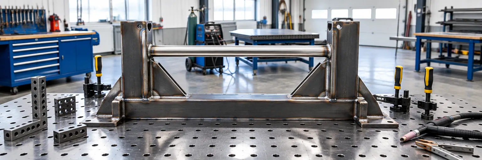
Welding design guide: joints, materials, symbols and limits
Learn how to design welded assemblies, choose weldable materials, size fillet welds, and call out welding symbols and inspections on drawings.
Welding joins materials by coalescence, usually by melting the joint with or without filler metal so the parts become a single continuous piece. Because welding applies intense local heat, a good weldment depends as much on joint access, part fit-up and material choice as on the weld size itself. This guide explains when to weld, how to design joints that hold their shape and strength, and how to specify welds clearly for your fabrication shop.
What welding is and when to use it
Welding unites parts into one continuous piece. Most shop processes are fusion welds that melt the joint, including arc welding (which uses an electric arc), resistance welding (which passes electric current through clamped parts), and laser beam welding (which focuses a light beam on the joint). Solid-state methods like friction stir welding and ultrasonic welding bond parts without melting them. Standard welding terms are defined in AWS A3.0M/A3.0.
Use welding for permanent, structural joints between parts of the same or closely related metals or thermoplastics. Typical parts include frames, enclosures, tanks, pressure-bearing assemblies, and fabrications built from cut sheet, plate, tube and extrusion. In published design guidance for sheet metal from a manufacturing service, MIG and TIG welding are the preferred processes because they produce strong, durable, leak-proof and permanent joints while lessening heat distortion.
Do not weld when parts must come apart for maintenance; use mechanical fasteners instead. Avoid fusion welding when joining dissimilar metal families (such as aluminum to steel), because mismatched thermal expansion and brittle intermetallic compounds weaken the joint. Where parts are heat-sensitive or made of dissimilar metals, consider a solid-state weld, brazing, soldering, adhesive bonding or fasteners.
Material weldability and filler selection
A material's suitability for welding depends on how it reacts to heat, cooling and shielding. Note that a general rating applies to the material family; a specific grade, section thickness and shop procedure can differ.
- Excellent weldability: Low-carbon steel (little risk of heat-affected zone hardening or cracking), high-strength low-alloy (HSLA) steel (weldable without preheat in usual thicknesses), austenitic stainless steel (use low-carbon L or stabilized grades where corrosion matters to avoid chromium carbide sensitization in the heat-affected zone), commercially pure titanium (requires full inert-gas shielding of the face, back side and cooling metal until cool because hot titanium absorbs oxygen and nitrogen from air and turns brittle), and thermoplastics like polyethylene, polypropylene and PVC.
- Good weldability: Wrought aluminum (5xxx and 6xxx alloys weld routinely with inert gas, though 2xxx and 7xxx alloys crack), chromium-molybdenum steel (such as 4130 tubing, welded with preheat and, for thick or highly stressed parts, post-weld stress relief), duplex stainless steel (needs matched filler and controlled heat input), precipitation-hardening stainless steel (welded in condition A, then re-aged), alpha-beta titanium, and nickel-copper alloys.
- Fair weldability: Medium-carbon steel and nickel-chromium-molybdenum steels (need preheat, interpass control and controlled cooling or tempering to prevent hard, brittle weld zones), ferritic stainless steel (keep heat input low to limit grain growth), cast aluminum (mostly repair welded, as porosity and silicon make it uncertain), nickel superalloys, and magnesium.
- Poor or unsuitable: High-carbon steel, martensitic stainless steel, cold-work tool steel and gray cast iron crack readily unless preheated and cooled slowly by a specialist; they are usually joined mechanically or brazed. Copper conducts heat away so fast that it demands high heat input and preheat, so brazing is often chosen instead. Technical ceramics cannot be welded at all.
For wrought aluminum welded by gas metal or gas tungsten arc, filler choice changes joint behavior. Published guidance from a welding consumable manufacturer gives two common rules:
- Choose 4043 (aluminum-silicon) filler to reduce hot-cracking risk (as on 6xxx alloys like 6061), to get a fluid, well-wetting pool and bright bead, or when the part runs in sustained service above about 65 °C (150 °F).
- Choose 5356 (aluminum-magnesium) filler when you need higher shear strength and ductility, or when the part will be anodized (5356 anodizes to a silver color close to the base metal, while 4043 turns dark gray). Do not use 5356 above about 65 °C (150 °F), where its magnesium content makes the weld susceptible to stress corrosion cracking.
Designing joints for access, fit-up and load
There are no universal numeric limits that cover every weldment; ask your shop or check the governing code for specific procedure values. Good weld design starts with geometry:
- Leave room for the torch and a line of sight: Place welds on the outside of structures and avoid deep corners or closed boxes. If a welder cannot reach and see the joint at a workable angle, the weld cannot be made or inspected properly.
- Design for the flat position: Where possible, design the assembly so the shop can orient or rotate it on a positioner to weld in the flat position. Gravity holds the molten pool in place when flat; vertical and overhead welds are slower and more prone to defects.
- Build fit-up into the parts: Cut and bend parts so they self-locate or sit cleanly in a fixture. A weld cannot bridge a gap that the welding procedure was not set up to fill.
- Match thicknesses at the joint: If a thick member meets a thin one in a butt or corner joint, the thick side conducts heat away and can stay unfused while the thin side burns through. Taper or thin the heavier member at the joint, or design the joint so heat can be aimed at the heavy side.
- Pick the right joint type: A full-penetration butt joint gives the most direct load path and best fatigue life, though thicker plate needs beveling and multiple passes. Lap, tee and corner joints with fillet welds require little edge preparation and fit up easily, but carry load less directly.
- Keep welds out of high-stress zones: Weld toes, roots and discontinuities concentrate stress and lower fatigue strength compared to base metal. Place welds away from peak stress locations and sharp section changes. When fatigue life matters, call for blending or grinding the weld toes.
Sizing fillet welds and controlling distortion
Weld volume grows with the square of the fillet leg size. A 5/16 in fillet holds about 1.6 times the weld metal of a 1/4 in fillet, putting much more heat into the part. Never oversize a weld "for safety"; size it for the calculated load and code minimum, and use intermittent welds instead of continuous welds wherever a continuous seal is not required.
Under the structural steel welding code AWS D1.1, a fillet weld's size on a drawing is its leg length, while the throat that carries the load is about 0.7 times the leg. AWS D1.1 sets minimum single-pass fillet weld leg sizes based on base metal thickness, not for strength, but because thick plate pulls heat out of a tiny weld too fast, causing the weld and heat-affected zone to harden and crack. For example, base metal up to 1/4 in (6 mm) thick requires at least a 1/8 in (0.125 in or 3 mm) fillet leg, while plate over 3/4 in (20 mm) requires at least a 5/16 in (0.3125 in or 8 mm) leg (the weld need not exceed the thinner part's thickness). Along the edge of a part in a lap joint, keep the maximum fillet size equal to the part thickness for parts under 1/4 in (6 mm), and 1/16 in (1.6 mm) short of the edge on parts 1/4 in (6 mm) or thicker, so the inspector can still see the corner and verify the weld size.
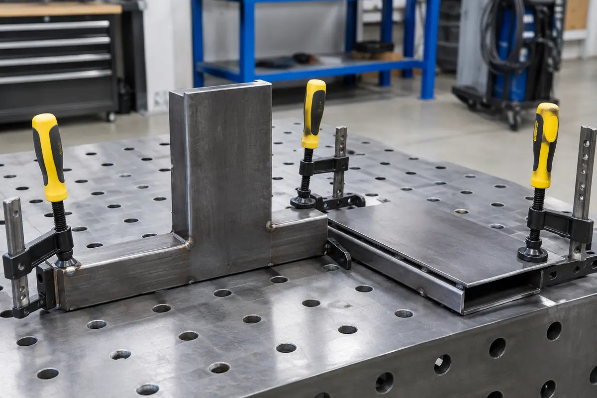
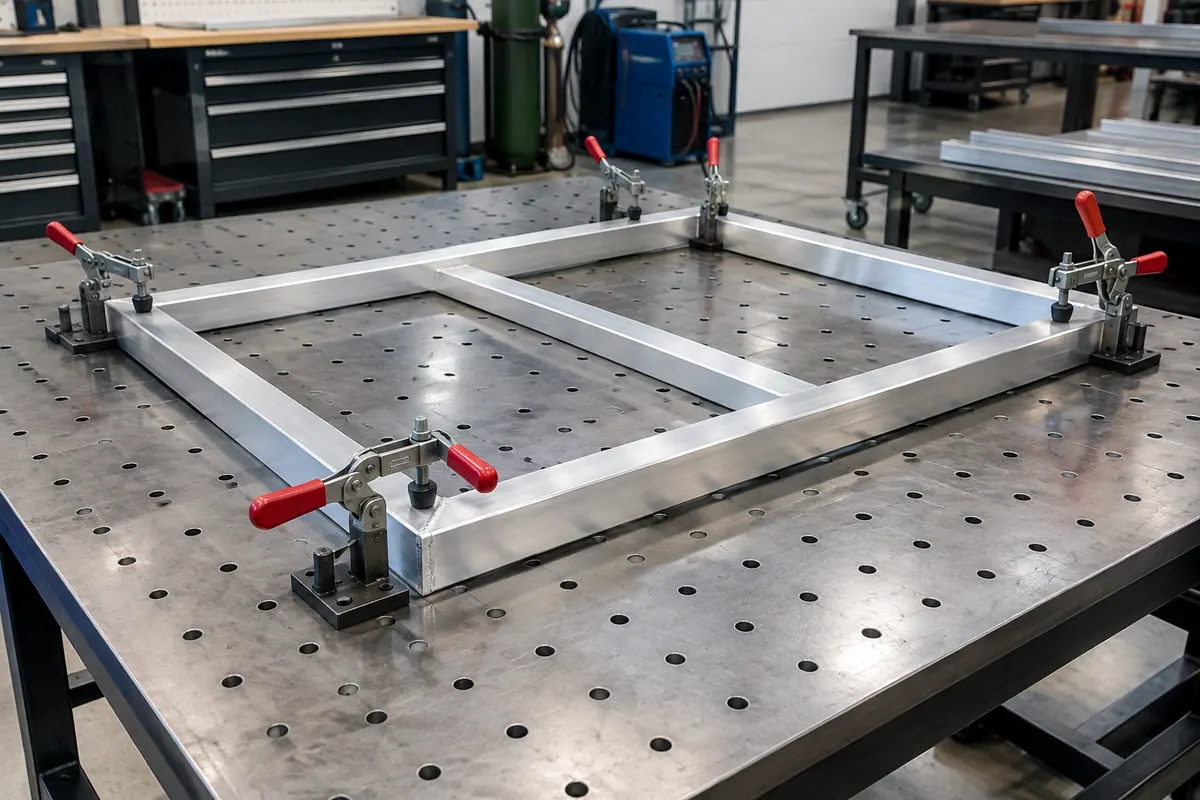
Every fusion weld heats a small zone that shrinks as it cools against the restraint of the colder surrounding metal, leaving residual stress and causing the part to bow, twist or pull in. Distortion is worst on thin, long, one-sided welds and in high-expansion metals like aluminum and austenitic stainless steel. To limit distortion, keep welds small, balance them symmetrically around the part's neutral axis, and let the shop alternate sides in a balanced sequence while clamping the part until cool.
What to watch out for: heat-affected zones and defects
Heat alters everything right beside the weld. The heat-affected zone (HAZ) is base metal that was heated high enough to change its microstructure without melting. In hardenable carbon and alloy steels, the HAZ can turn hard, brittle and crack-prone. In cold-worked or precipitation-hardened aluminum (such as T6 temper), welding overages or anneals the HAZ and softens it. Always design your joint to the reduced strength of the HAZ rather than the unwelded base metal, unless you plan for post-weld heat treatment (which can cause its own distortion).
Thick or hardenable steels require preheat and interpass temperature control to slow down cooling and avoid hydrogen-induced cold cracking. Under AWS D1.1 for common structural steels (Category B, such as ASTM A36 and A572 Grade 50) welded with low-hydrogen processes, metal up to 3/4 in (19 mm) thick needs a minimum preheat of 32 °F (0 °C), meaning if the steel is below 32 °F (0 °C), it must be heated to at least 70 °F (20 °C) before welding. For plates over 2-1/2 in (65 mm) thick, the code requires at least 225 °F (110 °C) preheat and interpass temperature.
Watch out for the four classic weld defects:
- Porosity: Gas pockets trapped in the freezing weld pool, caused by oil, grease, paint, rust, mill scale, moisture, aluminum oxide, damp consumables or poor gas shielding. Parts must be cleaned thoroughly before welding.
- Incomplete fusion and penetration: A weld bead can look fine on the outside while failing to fuse into the base metal or reach the joint root, usually from too little heat, fast travel, wrong torch angle, or poor joint prep.
- Cracks: Hot cracks open as the pool solidifies; cold cracks form after cooling when shrinkage stresses act on brittle, hydrogen-charged metal in rigid or thick joints.
- Undercut and surface flaws: Grooves melted into the base metal toe that concentrate stress.
Calling out welds, tolerances and inspection on drawings
Use standard welding symbols from AWS A2.4 on U.S. drawings. The symbol is built on a horizontal reference line attached to an arrow pointing at the joint:
- Arrow side vs. other side: A weld symbol placed below the reference line puts the weld on the arrow side of the joint. A symbol above the line puts it on the opposite (other) side. Symbols on both sides weld both sides.
- Size, length and pitch: For a fillet weld, write the leg size to the left of the triangle symbol, and the length and centre-to-centre pitch to the right. For example, "1/4 2-6" calls for a 1/4 in leg, 2 in long welds at a 6 in pitch. Omitting the length means weld the full length of the joint.
- All-around and field welds: A circle at the junction of the arrow and reference line means weld continuously all around the joint. A flag at the same junction marks a field weld to be made at the installation site rather than in the shop.
- Tail: Use the tail at the end of the reference line to note the welding process, a welding procedure specification (WPS), or a drawing note. Leave the tail off if no extra reference is needed.
If you send or receive drawings internationally, check the title block convention first. ISO 2553 uses a dashed reference line to identify the other side; reading an ISO symbol by AWS rules can put the weld on the wrong side of the part.
Reference the governing standards on your drawing: AWS D1.1/D1.1M for structural carbon and low-alloy steel, AWS D1.2/D1.2M for structural aluminum, and ISO 13920 when calling a general tolerance class for a welded construction instead of tolerancing every dimension. Finally, state how welds must be inspected: visual inspection catches surface flaws like undercut or overlap; dye penetrant or magnetic particle testing finds surface cracks; and ultrasonic or radiographic testing finds internal porosity or lack of fusion.
Design rules at a glance
| Rule | Value | Note | Source |
|---|---|---|---|
| Minimum fillet weld leg size (base metal up to 1/4 in / 6 mm) | 0.125 in (1/8 in / 3 mm) | AWS D1.1 single-pass minimum for carbon and low-alloy steel to prevent rapid-cooling cracks; need not exceed thinner part thickness. | [4] |
| Minimum fillet weld leg size (base metal over 1/4 to 1/2 in / 6 to 12 mm) | 0.1875 in (3/16 in / 5 mm) | AWS D1.1 single-pass minimum for carbon and low-alloy steel; check against calculated load size and use the larger. | [4] |
| Minimum fillet weld leg size (base metal over 1/2 to 3/4 in / 12 to 20 mm) | 0.25 in (1/4 in / 6 mm) | AWS D1.1 single-pass minimum for carbon and low-alloy steel. | [4] |
| Minimum fillet weld leg size (base metal over 3/4 in / 20 mm) | 0.3125 in (5/16 in / 8 mm) | AWS D1.1 minimum for carbon and low-alloy steel. | [4] |
| Maximum fillet leg along a lap joint edge (part 1/4 in / 6 mm or thicker) | Part thickness minus 1/16 in (1.6 mm) | AWS D1.1 rule so the original plate edge remains visible for weld size inspection (for parts under 1/4 in, max equals part thickness). | [4] |
| Equal-leg fillet weld throat thickness | 0.7 times leg length | Under AWS practice, drawings specify the leg length, while the throat carries the load. | [4] |
| Maximum service temperature for 5356 aluminum filler | 65 °C (150 °F) | Above this temperature, magnesium in 5356 can cause stress corrosion cracking; use 4043 instead (published vendor guidance). | [3] |
| Minimum preheat temperature (AWS D1.1 Category B steel, up to 3/4 in / 19 mm) | 32 °F (0 °C) | With low-hydrogen processes; if base metal is below 32 °F (0 °C), heat to at least 70 °F (20 °C) before welding. | [4] |
| Minimum preheat and interpass temperature (Category B steel, over 3/4 to 1-1/2 in / 19 to 38 mm) | 50 °F (10 °C) | AWS D1.1 for common structural steels (such as A36 and A572 Gr 50) using low-hydrogen processes. | [4] |
| Minimum preheat and interpass temperature (Category B steel, over 1-1/2 to 2-1/2 in / 38 to 65 mm) | 150 °F (65 °C) | AWS D1.1 for common structural steels using low-hydrogen processes. | [4] |
| Minimum preheat and interpass temperature (Category B steel, over 2-1/2 in / 65 mm) | 225 °F (110 °C) | AWS D1.1 for common structural steels using low-hydrogen processes. | [4] |
Common questions
- Should I specify 4043 or 5356 filler for welding 6061 aluminum?
- Both are used, depending on what the part needs. According to published filler guidance, choose 4043 when you want lower hot-cracking sensitivity on 6061, better pool wetting, or service temperatures above about 65 °C (150 °F). Choose 5356 when you need higher shear strength and ductility, or when the welded assembly will be anodized and needs a silver color match (4043 turns dark gray when anodized).
- Why does the steel welding code require a larger minimum fillet weld on thicker plate even for a light load?
- Thick steel plate acts as a heat sink and draws heat out of a small weld very quickly. Fast cooling creates a hard, brittle weld and heat-affected zone that can crack on its own. The AWS D1.1 minimum fillet leg sizes ensure enough heat input to slow down cooling; you must calculate the weld size required for your load and compare it against the code minimum, then specify whichever is larger.
- How does welding affect the strength of heat-treated aluminum like 6061-T6?
- The heat of fusion welding anneals or overages the metal right beside the weld, softening the heat-affected zone well below T6 base metal strength. You must design the joint around the lower heat-affected zone properties, or plan to heat-treat and re-age the entire assembly after welding (which can introduce distortion).
- What is the difference between a weld symbol above and below the reference line?
- On drawings following AWS A2.4, a weld symbol placed below the reference line tells the shop to put the weld on the arrow side (the side of the joint the arrow touches). A symbol above the line puts the weld on the opposite side. Always check whether foreign drawings use ISO 2553, which adds a dashed line to mark the other side.
- Can I fusion weld aluminum directly to steel?
- No, fusion welding dissimilar metal families like aluminum and steel is generally impractical because they have different melting points, thermal expansion rates and thermal conductivities, and they form brittle intermetallic compounds where they mix. Instead, use mechanical fasteners, adhesive bonding, brazing, or a solid-state joining method.