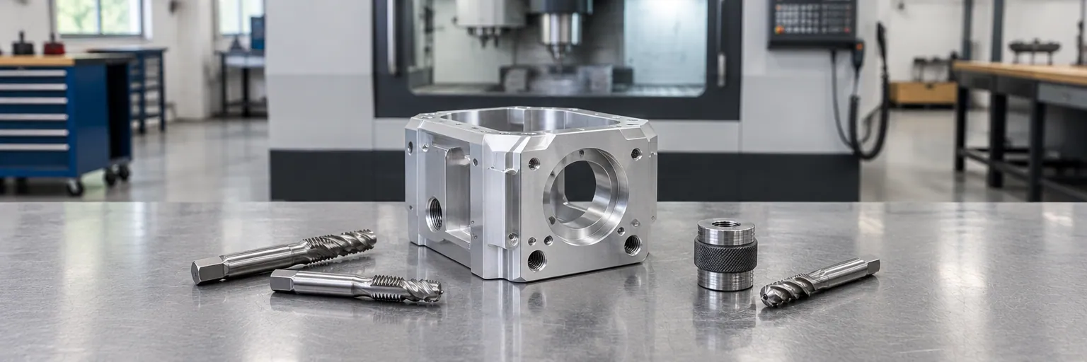
Tapping design guide: hole sizes, thread depth and blind holes
Learn how to design tapped holes for machining, choose between cutting and forming taps, size pilot holes, and avoid broken taps in blind holes.
Tapping cuts or forms an internal thread inside a drilled hole so a machine screw or bolt can fasten directly into a part. It is faster and less expensive than thread milling for common fastener sizes, requiring only a tap drill and a tap. Designing a reliable tapped hole means choosing standard thread sizes, keeping engagement depths reasonable, and leaving enough clearance at the bottom of blind holes.
What tapping is and how it works
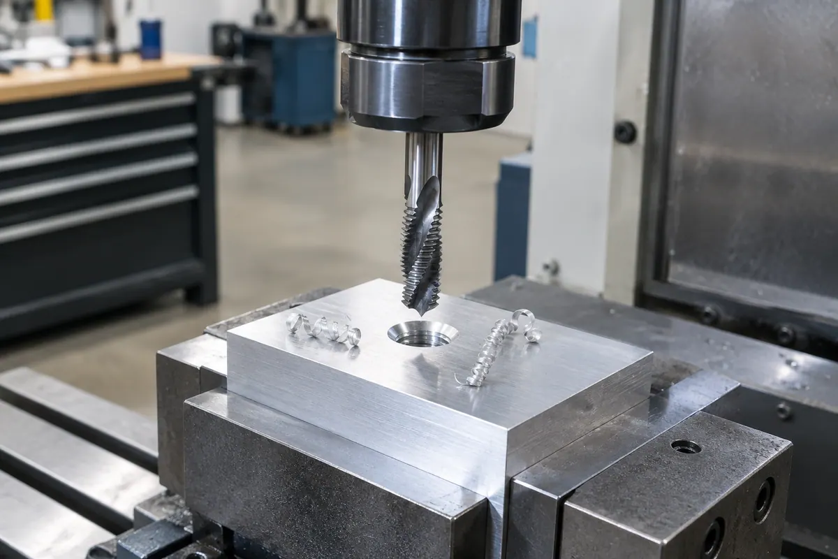
Tapping produces an internal thread in a pre-drilled hole using a multi-fluted tool called a tap. First, a tap drill makes a pilot hole near the minor diameter of the thread, and its mouth is chamfered so the tap starts square. The tap then enters the hole to cut or form the thread profile.
On a CNC machining center, the machine's tapping cycle synchronizes spindle rotation with the feed rate to match the thread pitch. In manual operations on a drilling machine, the machine chuck is used only to hold and align the tap while the machinist turns it by hand.
On an engine lathe, a machinist can hand-tap by locking the spindle, supporting the tap with the tailstock center, and turning the tap with a wrench. Power tapping on a lathe is reserved for taps 1/2 in and larger (never in steel) at 10 to 30 rpm with plenty of cutting fluid and the tap wrench resting on the compound rest. External threads can be cut in a similar way using a hand die pushed square against the work by the tailstock.
When to tap vs. thread mill or use inserts
Tapping is the standard choice for threading fastener holes in parts small enough to fit on a machine. It is quicker and cheaper than thread milling because it uses simple, dedicated tooling.
Published guidance from manufacturing services varies on where to switch from tapping to thread milling or single-lip CNC threading tools:
- Taps and dies can cut threads down to a minimum feasible size of M2, though M6 and larger is preferred because small taps break easily.
- Some published guidelines recommend using traditional cutting or forming taps up to M6 and switching to a single-lip cutting tool above M6, where larger taps demand more machine horsepower.
- Other service guidelines use taps below M6 and CNC threading tools above M6 to thread blind holes to their full depth.
Confirm with your shop which method they prefer for your thread size and material. Choose thread milling on a machining center instead of tapping when you have large threads, very hard materials, thin walls, or critical blind holes where a broken tap cannot be risked. In soft aluminum or plastics where threads strip easily under load, use threaded inserts rather than relying on direct tapped threads.
Cutting taps vs. forming taps
Shops make internal threads with either cutting taps or thread-forming (roll) taps. Ask your shop which type they use in your material, as the pilot hole size depends on the method.
- Cutting taps remove material to create the thread and have flutes that give chips room to escape and let coolant or lubricant reach the cutting edge. Use a cutting tap in hard materials.
- Forming taps displace metal instead of cutting it, pushing material up from the hole wall to form the thread crests. Use a forming tap in soft, non-ferrous metals such as aluminum, brass, copper, or lead, as well as ductile low-carbon steel or materials that produce long ribbons instead of chips.
Never use a cutting-tap drill size for a forming tap. Because a forming tap displaces metal, it requires a larger pilot hole taken from the forming tap manufacturer's table; a standard cutting-tap hole will overload and break a forming tap. Also note that the displacing forces of a forming tap tend to distort the entry hole and the exit of a through hole.
Hole sizing and thread percentage
When preparing a 3D CAD model for CNC machining, one service's guideline is to model pilot holes slightly narrower than the minor diameter of the thread. Stick to standard thread sizes common in your region so the shop has standard tooling on hand.
For cutting taps in general-purpose threads, standard tap drill tables are sized to produce about 75 percent of full thread depth. Specifying more than 75 percent thread depth adds almost no strength because the outer portion of the thread form carries very little load, while tapping torque and the risk of breaking the tap rise sharply. In tough or work-hardening materials like stainless steel and titanium, or in deep holes, 60 to 65 percent thread engagement is enough.
For ISO metric threads (coarse or fine) made with a cutting tap, calculate the tap drill diameter by subtracting the pitch from the nominal diameter:
- M6 x 1 (6 mm nominal diameter, 1 mm pitch) uses a 5.0 mm (0.197 in) tap drill for a class 6H thread.
- M10 x 1.5 (10 mm nominal diameter, 1.5 mm pitch) uses an 8.5 mm (0.335 in) tap drill for a class 6H thread.
Thread depth, blind holes, and part geometry
The first few threads carry most of the fastener's load. Engagement beyond 1.5 times the nominal diameter adds little strength, so keep total thread length to about 3 diameters or less. Published service guidelines consider any thread deeper than 1.5 diameters a deep hole; going deeper increases tool-to-part contact, heat, cutting force, and tap breakage risk. Deeper holes require taps with larger flutes and lower cutting speeds and feeds. If a through hole is deeper than the tool can reach, you must either leave the bottom section unthreaded or tap from both ends (which leaves an unaligned junction or an unthreaded band in the middle).
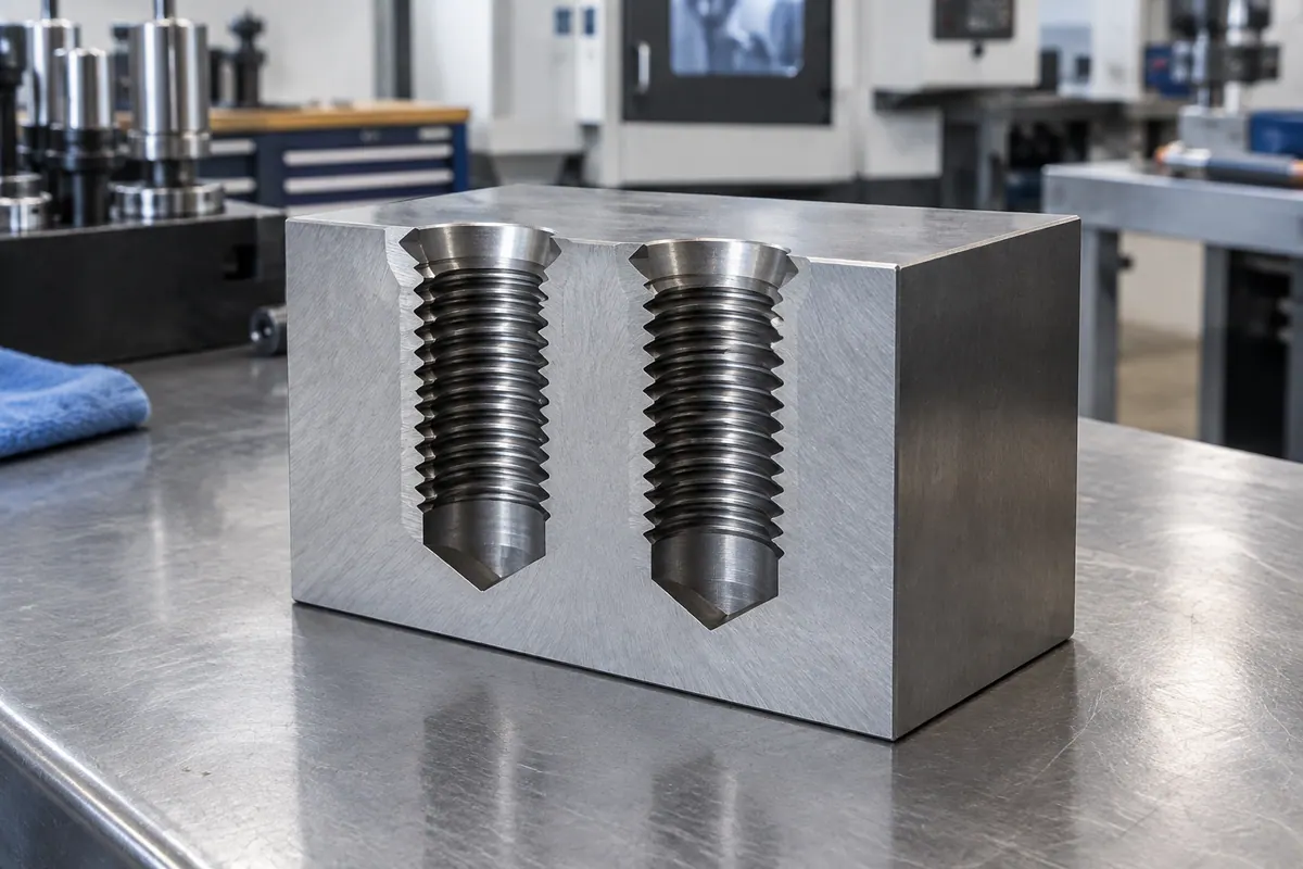
In a blind hole, a tap's chamfered lead cannot cut full threads all the way to the bottom, and chips packed at the bottom will break the tap. Always drill a blind hole deeper than the required full-thread depth:
- For threads below M6 made with a tap, published service guidelines recommend adding an unthreaded relief at the bottom equal to at least 1.5 times the nominal diameter.
- To get threads closer to a flat (end-milled) or conical (drilled) bottom, shops can use a plug or bottoming tap, or a spiral-flute tap that lifts chips upward out of the hole.
Check your part geometry around the hole as well:
- Keep the entire outer diameter of the thread inside the part walls. If a thread is too close to an edge, it can break through the side wall, ruin the surface finish, weaken the part, or snap the tap. Add a boss if the wall is too thin.
- Never drill and tap directly into an angled surface, because asymmetric bending stresses will break the tap. Either machine a flat pocket first and tap into that flat face, or tap the hole into a flat surface first and machine the angle afterward.
Drawing callouts and common mistakes
On your 2D engineering drawings, specify the thread series (such as UNC, UNF, or metric) and the minimum thread engagement depth. For blind holes, always dimension the drilled-hole depth and the full-thread depth separately. Specify a thread class (such as ISO 6H) only where the fit requires it, and ask your shop which classes they routinely hold in your chosen material. Applicable standards include ASME B1.1 for unified inch threads and ISO 261 and ISO 965-1 for metric threads.
Watch out for these common tapping failures during design and shop prototyping:
- Drilling the pilot hole to the thread's major diameter instead of the tap-drill size, which leaves no material for the threads.
- Packing chips into the bottom of a blind hole, letting flutes get dirty, or starting a tap off the hole axis. When hand tapping metals, clean chips out of the hole first and back the tap off frequently to break chips.
- Galling and work-hardening in stainless steel and titanium, or stripping threads out of soft aluminum and plastics.
- Forcing a tap into a 3D-printed plastic part, which splits or fractures the layers. Keep the tap wrench perpendicular, cut slowly, reverse regularly to clear debris, and test-fit the screw before final assembly.
- Turning a coarse external hand die in a single pass. Open the adjustable die to rough-cut the thread first, then close it to finish to size with plenty of lubricant.
Design rules at a glance
| Rule | Value | Note | Source |
|---|---|---|---|
| Minimum feasible thread size (taps and dies) | M2 (2 mm / 0.079 in) | Published service minimum; M6 and larger is preferred to avoid breaking small taps. | [3] |
| Preferred thread size threshold | M6 (6 mm / 0.236 in) | Taps are standard up to M6; above M6, shops often switch to single-lip CNC threading tools. | [4] |
| Deep thread depth-to-diameter ratio | 1.5 x diameter | Engagement beyond 1.5xD adds little strength and raises heat, cutting force, and breakage risk. | [4] |
| Maximum recommended thread length | About 3 x diameter | Keep tapped thread lengths at or below three diameters. | [1] |
| Blind hole unthreaded bottom relief (below M6) | 1.5 x nominal diameter | Published guideline for tapped blind holes to leave room for the tap chamfer and chips. | [3] |
| Standard thread depth percentage (cutting taps) | About 75% | Standard tap drill tables target 75% thread; deeper thread adds torque without adding strength. | [5] |
| Thread depth percentage for tough materials or deep holes | 60% to 65% | Recommended for work-hardening alloys like stainless steel and titanium to prevent tap breakage. | [5] |
| Tap drill size for M3 x 0.5 (cutting tap, class 6H) | 2.5 mm (0.098 in) | Nominal diameter minus pitch, producing about 75% of full thread. | [5] |
| Tap drill size for M6 x 1 (cutting tap, class 6H) | 5.0 mm (0.197 in) | Nominal diameter minus pitch, producing about 75% of full thread. | [5] |
| Tap drill size for M8 x 1.25 (cutting tap, class 6H) | 6.8 mm (0.268 in) | Nominal diameter minus pitch, producing about 75% of full thread. | [5] |
| Tap drill size for M10 x 1.5 (cutting tap, class 6H) | 8.5 mm (0.335 in) | Nominal diameter minus pitch, producing about 75% of full thread. | [5] |
| Minimum tap size for lathe power tapping | 1/2 in at 10 to 30 rpm | Use plenty of cutting fluid; never power tap on a lathe in steel or with taps under 1/2 in. | [2] |
Common questions
- How deep should I design a tapped hole?
- Design most tapped holes with an engagement depth of about 1.5 times the nominal thread diameter, and do not exceed 3 diameters. The first few threads carry the vast majority of the load. Going deeper than 1.5 diameters adds very little holding strength while generating more heat, requiring more cutting force, and increasing the chance of snapping a tap.
- How much clearance do I need at the bottom of a blind tapped hole?
- Always drill the pilot hole deeper than the required full-thread depth to accommodate the tap's chamfered lead and to give chips a place to go. For threads smaller than M6, published service guidelines recommend leaving an unthreaded length equal to 1.5 times the nominal diameter at the bottom of the hole. Always call out both the drill depth and the full-thread depth on your 2D drawing.
- Can I use the same pilot hole size for a cutting tap and a forming tap?
- No. A forming (roll) tap does not cut chips; it displaces metal from the hole wall upward to create the thread crests. Because of this, it requires a larger pilot hole than a cutting tap. Using a standard cutting-tap drill size will overload and break a forming tap, so always size the hole from a forming tap table.
- Why should I reduce thread engagement from 75% to 60% in stainless steel or titanium?
- Stainless steel and titanium are tough materials that work-harden and gall during tapping. Standard tap drill charts give about 75% thread depth, but the outermost tip of the thread form carries almost no load. Dropping to 60% or 65% thread depth by using a slightly larger tap drill sharply reduces tapping torque and prevents broken taps with negligible loss in thread strength.
- How do I put a tapped hole into an angled surface?
- Do not drill and tap directly into a sloped face, because the uneven contact puts bending stress on the tool and breaks traditional taps. Either machine a flat pocket into the angled face first so the tap enters perpendicular to the flat bottom, or drill and tap the hole into a flat surface before machining the angled feature.