Sheet metal design guide: bends, holes, flanges and tolerances
Design sheet metal parts shops can build. Learn rules for bend radius, flange height, hole spacing, bend relief, clinch hardware and tolerances.
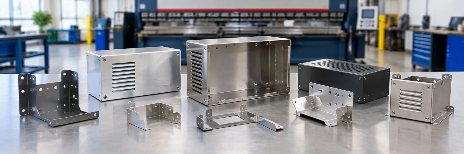
Sheet metal forming turns flat stock into stiff, lightweight enclosures, brackets, chassis and covers without changing the sheet's thickness. Most prototypes and low-to-mid-volume parts are cut flat and bent on a CNC press brake using standard punch-and-die tooling. Designing around how the metal stretches and how the brake tooling contacts the sheet prevents cracked bends, oval holes and unexpected manual quotes.
What it is and when to use it
Sheet metal forming shapes flat rolled stock by bending, stretching or drawing while keeping a uniform gauge throughout the part. Because every part starts as one flat sheet, you cannot design a part that is 1/16 in thick in one zone and 1/32 in thick in another. Adding bends stiffens thin sheet across multiple axes, letting a formed skin replace a heavy machined block at a fraction of the material and cost.
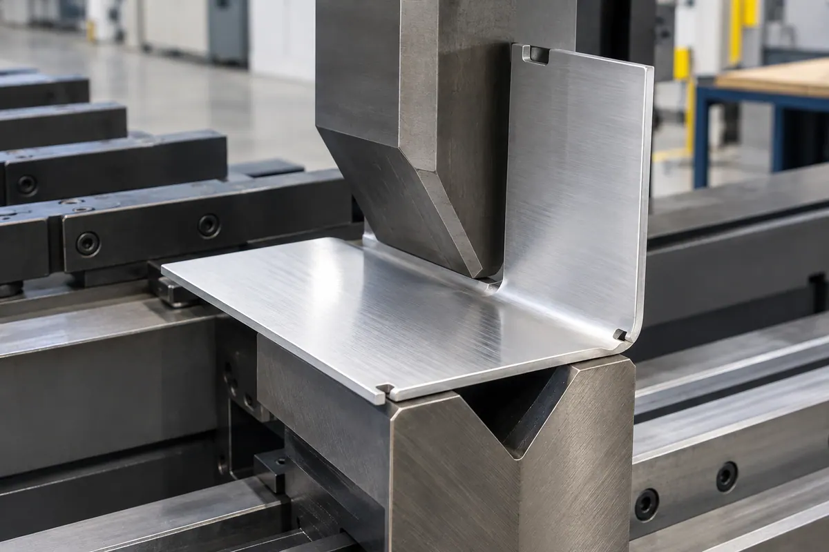
Press-brake bending is the workhorse process for flat patterns with flanges, from one part to a few thousand, because it uses standard V-dies and punches rather than part-specific tooling. As the punch pushes the sheet into the die, the outer fibers stretch and thin while the inner fibers compress and thicken. Shops use three main methods on a press brake:
- Air bending touches the sheet only at the punch tip and the two die shoulders, allowing one tool set to form any angle at the lowest force.
- Bottoming presses the sheet into the die faces for higher angle accuracy.
- Coining uses very high pressure to set the angle almost exactly and eliminate springback.
For high volumes of stamped blanks, deep-drawn cups or roll-formed profiles, custom dies pay off. For perforated panels, louvers, knockouts and enclosures with many repeated cutouts, CNC turret punching shears holes rapidly without laser heat, though a laser handles one-off contours and thicker stock.
Choosing sheet materials and gauges
Pick sheet stock based on ductility, machinability, weldability, tensile strength, corrosion resistance, weight and cost. Low-carbon steel, austenitic stainless steel and pure copper rate excellent for forming; aluminum, high-strength low-alloy (HSLA) steel, ferritic stainless steel and commercially pure titanium rate good.
Watch the alloy and temper when bending:
- Aluminum: Prefer 5xxx-series alloys such as 5052-H32 or 5754 over 6xxx-series alloys. 5052 forms readily, whereas 6061-T6 is slightly brittle and cracks on tight bends unless given a larger radius.
- Steel and stainless: Mild steel bends predictably. Stronger HSLA steels spring back more and require larger bend radii. Austenitic stainless steels (such as 304 and 316) work-harden during bending, which raises both forming force and springback.
As an example of service stock ranges, Hubs recommends 0.5 mm to 6 mm (0.020 in to 0.236 in) sheet for press-brake bending. Protolabs stocks steel, stainless steel and aluminum from 0.024 in to 0.250 in (0.61 mm to 6.35 mm), and copper and brass from 0.025 in to 0.093 in (0.635 mm to 2.36 mm). Protolabs cuts flat parts down to 0.250 in square and formed parts down to 0.500 in square, up to a maximum envelope of 39 in by 47 in (990.6 mm by 1,193.8 mm). Always confirm your shop's stocked gauges and bed limits.
Bends, bend radius and flat patterns
Never design a completely sharp internal corner on a bent part. A radius too tight for the alloy, thickness or grain direction causes cracks on the outer surface where tensile stress peaks. For cold bending of flat rolled steel, the German standard DIN 6935 sets the smallest permissible inside bend radii by grade, thickness and rolling direction, as well as flat blank length.
In general shop practice, Hubs recommends an inside bend radius at least equal to the sheet thickness. Protolabs recommends a 0.030 in (0.762 mm) inside radius across all flanges, noting that its standard tooling spans 0.010 in to 0.250 in (0.254 mm to 6.35 mm) with standard radii of 0.030, 0.060, 0.090 and 0.120 in. Whatever radius you choose, call out the same internal radius on every flange and keep bend orientations consistent across the part so the operator does not have to change setups.
Because bending stretches the metal, the neutral axis shifts toward the inner surface. Flat-pattern development uses the K-factor (the ratio of the neutral-axis offset from the inner face to the material thickness), which runs from 0.3 to 0.5 and averages 0.4468. In published tables, air bending with an inside radius up to 1 thickness uses a K-factor around 0.33 for soft materials like aluminum, 0.38 for carbon steel and 0.40 for stainless steel, rising to 0.40, 0.43 and 0.45 respectively when the radius is 1 to 3 thicknesses. Bottom bending tight radii starts around 0.42. From the K-factor, CAD software computes the bend allowance (arc length along the neutral axis) and bend deduction (bend allowance minus twice the outside setback; for a 90-degree bend, outside setback equals inside radius plus thickness). When flat-pattern accuracy is critical, have the shop bend three to five test pieces to measure the exact value.
Flanges, bend relief, hems and curls
Flanges must be tall enough to span the V-die opening and make proper contact with the tooling without deforming. In the Hubs design guide, minimum flange height (bend height) is at least 2 times the material thickness plus the inside bend radius (2t + R). Protolabs specifies that flanges must be at least 4 times the material thickness long so the sheet makes three points of contact in the tooling.
Where a bend stops next to unbent material, or where two adjacent flanges meet at a corner, the metal will tear or bulge outward unless you relieve it. Add a bend relief notch on each side of a bounded bend at least 1 material thickness wide, or roughly 0.030 in (0.762 mm) wide where two flanges meet. Relief cuts also reduce springback and add stiffness; if the corner must be sealed, the shop can weld the junction after forming.
For safe edges and added stiffness, you can fold the edge into a hem or roll it into a curl:
- A hem folds the sheet back on itself to leave a rounded exposed edge, though the raw edge remains accessible; avoid completely flat hems when fracture is a risk.
- A curl rolls the edge into a hollow ring that fully encloses the raw edge or acts as a hinge knuckle.
Hems and curls take two or three forming stages and custom tooling. On automated quoting platforms like Xometry, hems, curls, rolled sheets, stampings and weldments are routed to manual review.
Holes, slots, notches, tabs and countersinks
Features cut into the flat blank will stretch out of shape if they sit too close to a bend or edge. Keep holes and slots at least 4 times the material thickness from any bend line or inside corner; a round hole closer than 4 thicknesses to a bend stretches into an egg shape. If a feature must sit closer, either extend the cutout across the bend line, relieve it, or have it machined after forming at added cost.
For feature sizes and edge distances, Protolabs and Xometry publish the following service guidelines (confirm exact limits with your shop):
- Hole diameter: Make holes and slots at least the material thickness in diameter. In turret punching, a punch narrower than the sheet thickness will break.
- Hole-to-edge distance: In Protolabs' guide, keep holes at least 0.062 in (1.57 mm) from the edge in sheet 0.036 in (0.914 mm) or thinner, and at least 0.125 in (3.18 mm) from the edge in thicker sheet.
- Notches and tabs: Make notches at least 1 thickness or 0.040 in (1.02 mm) wide, whichever is greater. Make tabs at least 2 thicknesses or 0.126 in (3.20 mm) wide, whichever is greater. Neither a notch nor a tab should be longer than 5 times its width.
- Countersinks: Use a standard angle of 82, 90, 100 or 120 degrees and a major diameter between 0.090 in and 0.500 in (2.29 mm and 12.7 mm). Xometry recommends keeping countersink depth to at most 0.6 times the sheet thickness, spaced at least 8 thicknesses from another countersink, 4 thicknesses from an edge and 3 thicknesses from a bend.
When hole location or diameter is critical, specify CNC milling, which is the most precise method; turret punching and laser cutting sit in the middle, and hand drilling is the least precise.
Self-clinching hardware
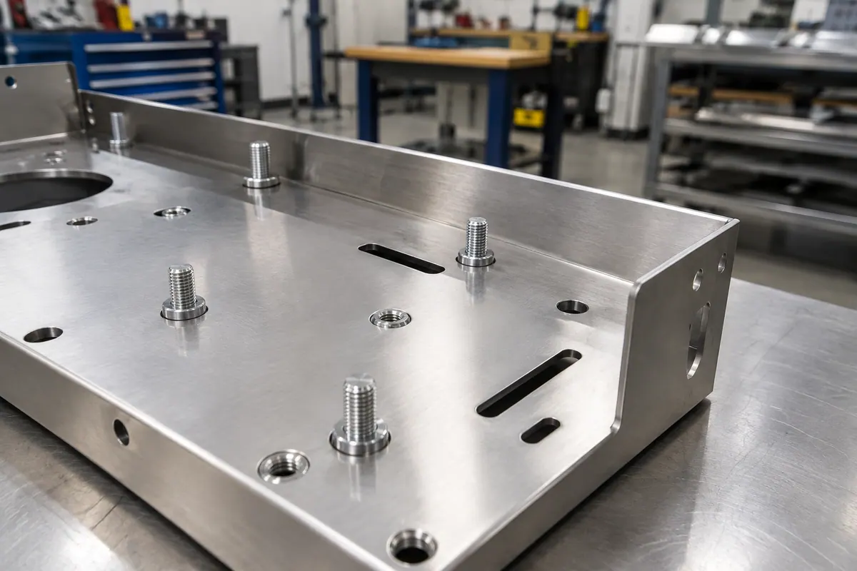
Sheet metal is rarely thick enough to tap directly with machine threads. Instead, use self-clinching nuts, studs or standoffs, or cage nuts, and model a plain mounting hole sized to the fastener manufacturer's specification in the flat blank.
Clinching works by pressing the fastener into the hole so cold-formed sheet metal flows into an undercut around the fastener's shank. Two clearance rules prevent installation failures:
- Edge and hole distance: Always respect the hardware maker's minimum centerline-to-edge distance (such as PEM's published minimum). Placing a mounting hole closer than that minimum to an edge, cutout or adjacent hole causes the sheet to bulge outward rather than lock into the fastener.
- Punch clearance near bends: The installation press needs room for its flat punch above the part and anvil below it. Leave at least the 0.5 in (12.7 mm) installation punch head diameter clear around the fastener, and allow extra clearance near bends and form features so the press tool does not collide with the flange.
Tolerances, finishes and drawing callouts
Sheet metal tolerances are looser than CNC machining tolerances because bending stretches the metal, and every added bend compounds variation across the part. Specify tight tolerances only on critical features to keep costs down. General tolerances for sheet metal parts are covered by ISO 2768-1, which you can call out on a drawing by its tolerance class when vendor defaults do not apply.
Published service defaults show what shops typically hold without special fixtures (always verify with your supplier):
- Protolabs holds ±0.005 in (0.13 mm) on flat features (edge-to-edge, edge-to-hole and hole-to-hole on one face) in sheet under 0.13 in (3.30 mm) thick, and ±0.015 in (0.38 mm) in thicker stock. For bends in sheet under 0.13 in, defaults are ±1 degree on bend angle, ±0.010 in (0.25 mm) bend-to-edge, ±0.015 in (0.38 mm) bend-to-bend, bend-to-hole and across two bends, and ±0.030 in (0.76 mm) across three or more bends (adding 0.010 in to linear values for sheet over 0.13 in). Formed countersink diameters default to +0.020 in / -0.010 in (+0.51 mm / -0.25 mm).
- Xometry holds ±0.010 in (0.25 mm) between features on the same surface, ±0.015 in (0.38 mm) from edge to bend or bend to hole, ±0.030 in (0.76 mm) across a bend or on overall formed dimensions, and ±1 degree on bend angles.
Keep three shop practices in mind when preparing your drawing:
- Raw stock thickness: The tolerance on wall thickness is the mill tolerance of the raw sheet stock, not a fabrication tolerance.
- Edge breaking: Shops break and deburr sharp edges on formed parts by default, and punched holes require deburring to remove the bottom rollover burr. If a functional edge must remain sharp, call it out on the drawing.
- Cosmetic surfaces: Press brake dies leave witness lines along the outside of bends unless the shop uses a urethane slip sheet, blends the surface or applies a full-coverage finish.
Design rules at a glance
| Rule | Value | Note | Source |
|---|---|---|---|
| Recommended sheet thickness (press brake) | 0.5 mm to 6 mm (0.020 in to 0.236 in) | Hubs general guideline; Protolabs stocks 0.024 in to 0.250 in (0.61 mm to 6.35 mm), copper/brass to 0.093 in. | [2] |
| Minimum inside bend radius | >= 1x thickness (or 0.030 in / 0.762 mm) | Hubs rule is >= 1t; Protolabs uses 0.030 in standard radius for ~95% of parts; 6061-T6 needs larger. | [2] |
| Minimum flange height and length | Height >= 2t + R; Length >= 4t | Height rule from Hubs (t = thickness, R = inside radius); length rule from Protolabs for 3-point tool contact. | [1] |
| Bend relief width | >= 1x thickness (or ~0.030 in / 0.762 mm) | Add on each side of a bounded bend or where two flanges meet to prevent tearing and bulging. | [2] |
| Minimum hole and slot diameter | >= 1x thickness | Punches narrower than the sheet thickness break. | [4] |
| Hole and slot distance to bend line | >= 4x thickness | Prevents holes from stretching into an oval during bending. | [3] |
| Hole distance to edge | >= 0.062 in (<=0.036 in stock); >= 0.125 in (>0.036 in stock) | Protolabs guideline (1.57 mm and 3.18 mm) to prevent edge distortion; Hubs also cites 4t from edges. | [4] |
| Minimum notch and tab width | Notch >= 1t or 0.040 in; Tab >= 2t or 0.126 in | Protolabs guideline; use whichever value is greater. Maximum length is 5x width for both. | [4] |
| Countersink depth and spacing | Depth <= 0.6t; Spacing >= 8t apart, 4t to edge, 3t to bend | Xometry guideline; Protolabs specifies 0.090 in to 0.500 in major diameter at 82°, 90°, 100° or 120°. | [6] |
| Clinch hardware installation clearance | >= 0.5 in (12.7 mm) punch head diameter | Protolabs guideline; allow more near bends and follow hardware maker's minimum centerline-to-edge distance. | [8] |
| K-factor range for flat patterns | 0.3 to 0.5 (0.4468 average) | Dimensionless ratio; ~0.33 for tight air bends in soft metal, rising toward 0.5 for larger radii and harder alloys. | [2] |
| Single-surface feature tolerance | ±0.005 in (<0.13 in stock) to ±0.015 in (>0.13 in stock) | Protolabs default (0.13 mm to 0.38 mm); Xometry standard is ±0.010 in (0.25 mm) on the same surface. | [4] |
| Across-bend and angle tolerances | ±0.015 in to ±0.030 in linear; ±1° angle | Vendor defaults for 1 to 3+ bends (0.38 mm to 0.76 mm); confirm with shop and supply a drawing for tighter. | [1] |
Common questions
- Why should I choose 5052 aluminum instead of 6061-T6 for bent sheet metal parts?
- 6061-T6 is a heat-treated temper that is slightly brittle and prone to cracking along the outer surface of tight bends. 5xxx-series alloys such as 5052-H32 and 5754 are much more ductile and form cleanly at standard press-brake radii. If your design requires 6061-T6, give the bends a larger inside radius than the standard 0.030 in (0.762 mm).
- How close can I put a hole to a bend line without it distorting?
- Keep holes and slots at least 4 times the material thickness away from any bend line or inside corner. Closer than 4 thicknesses, the stretching metal near the bend pulls a round hole into an oval shape. If a cutout must sit closer, extend it all the way through the bend line or have the hole machined after forming.
- Why do I need to use the same bend radius on every flange?
- Each internal bend radius requires a matching punch in the press brake. Calling out a single radius (such as a shop's standard 0.030 in / 0.762 mm tool) and keeping bend orientations consistent lets the operator form the entire part in one setup, which lowers setup time and part cost.
- Can I tap threads directly into a sheet metal part?
- Sheet metal gauges are usually too thin to hold enough threads directly. Instead, model a plain hole sized to the fastener manufacturer's specs and specify a self-clinching nut, stud or standoff, or a cage nut. Keep the hole at least the manufacturer's minimum distance from any edge, and leave at least a 0.5 in (12.7 mm) clearance diameter for the installation punch.
- How is the flat pattern length calculated for a bent part?
- As sheet metal bends, the outer surface stretches and the neutral axis shifts inward. The flat pattern uses a K-factor (typically 0.3 to 0.5, averaging 0.4468) to find the bend allowance along the neutral axis, then subtracts the bend deduction (bend allowance minus twice the outside setback) from the sum of the outside flange lengths. When flat-pattern accuracy is critical, shops bend three to five test pieces to measure the exact K-factor for that gauge, alloy and die.