Press fit design guide: interference, tolerances and materials
How to design press-fit and shrink-fit joints, select interference grades, specify standard tolerance classes, and prevent galling or cracking.
Press fitting holds a shaft, pin, bushing, or bearing inside a slightly smaller bore using only elastic stress and friction at the interface. Because the joint relies on no bolts, keys, or adhesives, its strength depends entirely on tolerance control, material properties, and clean assembly. This guide covers when to use a press fit, how to size interference and specify tolerances, and how to avoid part failure.
What press fitting is
Press fitting is an interference-fit assembly method where an inner part is forced into a slightly smaller hole. The elastic deformation between the mating parts creates radial contact pressure, holding the joint together by friction alone without separate fasteners.
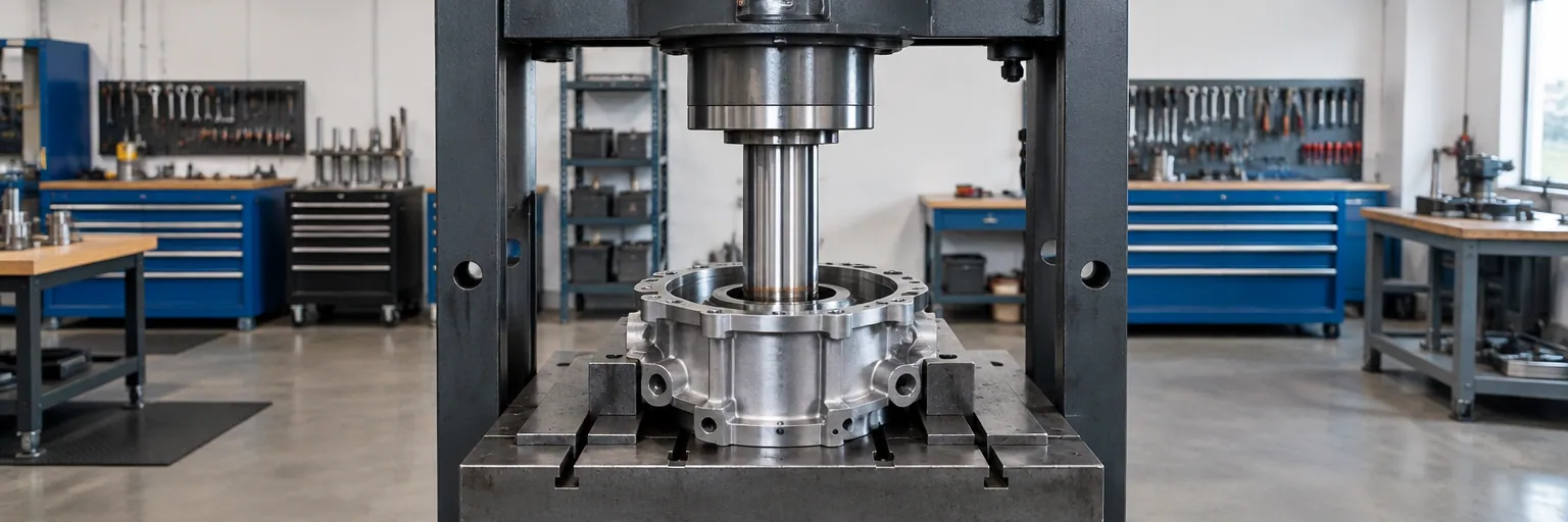
Shops assemble force fits mechanically using an arbor press for moderate loads or a hydraulic press for high-interference joints. Insertion forces on a press typically range from 500 to over 20,000 pounds. When a joint requires higher interference or you must avoid axial insertion stress, shops use a shrink fit instead. In a shrink fit, the outer part is heated to 150 to 300 °C or the inner part is cooled in liquid nitrogen to about -196 °C so the pieces slip together with clearance and lock as they return to ambient temperature.
When to use it
Use a press fit when a round part must sit securely in a bore without rotating or slipping axially, and without adding bolts, screws, keyways, or adhesives. Typical applications include:
- Bearing races pressed into housings or onto shafts so the race cannot creep and fret
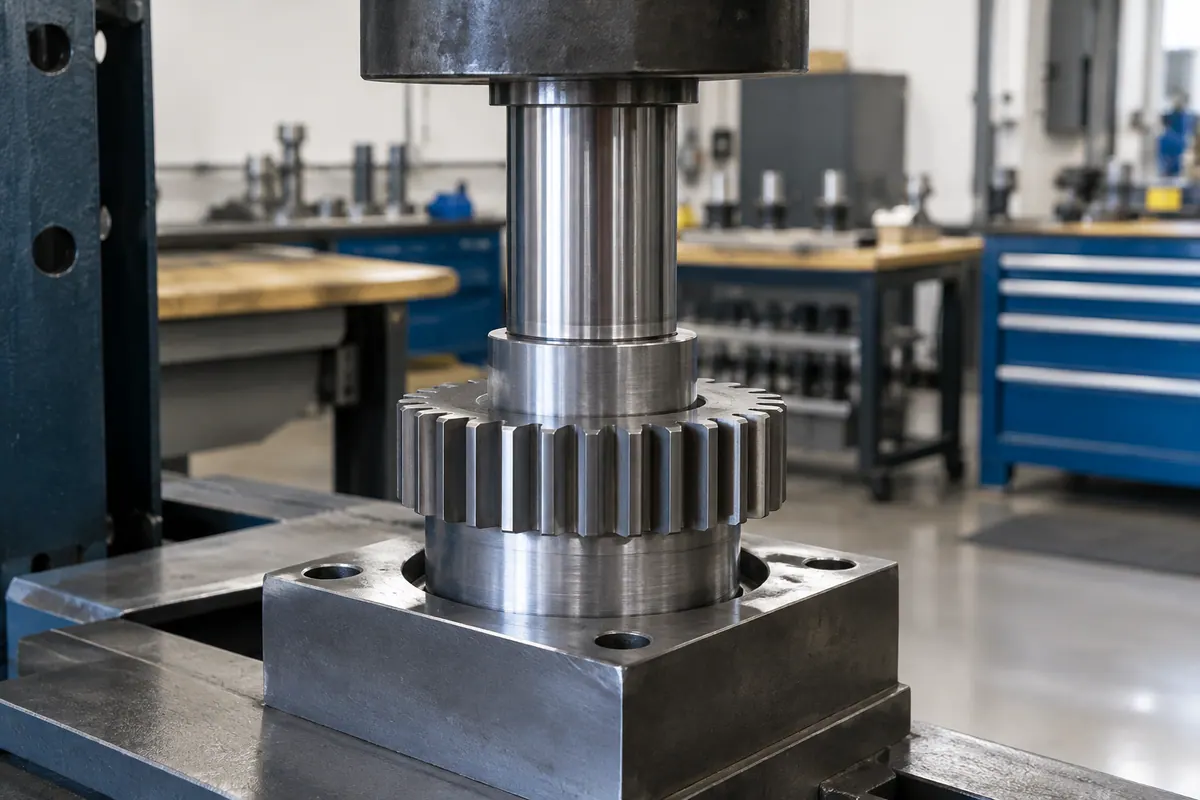
- Gears mounted on shafts to transmit torque without a keyway or spline
- Rotor cores, commutators, and impellers on motor shafts
- Alignment dowels and cylindrical bushings
Match the fit grade to the load and maintenance needs. Use a light press fit for thin-walled or brittle parts, a drive fit (assembled with a mallet or light press) if the joint must occasionally come apart without damage, and a force fit or shrink fit for permanent joints under heavy axial or rotational loads.
Do not use a transition fit (where the shaft-to-bore difference is roughly -0.001 to +0.001 in) if you need guaranteed retention or torque transfer. Transition fits do not create interference in every mated pair and belong only in locating applications. If an assembly must come apart routinely, use threaded fasteners; if you are joining plastic housings, use snap fits.
Sizing interference and stress
Interference controls holding force, but more interference also raises the risk of yielding ductile bores or cracking brittle ones. Calculate the minimum interference needed for your applied load, and use the Lamé thick-walled cylinder equation to keep contact stress below 70% to 80% of the material's yield strength.
Published guidance from manufacturing services such as Xometry groups press fits into general interference ranges (confirm specific capabilities with your shop):
- Light press fit: 0.0005 to 0.001 in (0.013 to 0.025 mm) for thin-walled or brittle parts
- Drive fit: 0.001 to 0.002 in (0.025 to 0.051 mm) for occasional disassembly
- Force fit: 0.003 to 0.005 in (0.076 to 0.127 mm) for continuous heavy loads
- Heavy press fit: above 0.005 in (0.127 mm) on large diameters for permanent structural joints
For permanent joints, select an interference whose axial retention exceeds the maximum pull-out load by a safety factor of 1.5 to 2.5. For joints carrying torque, torque capacity equals the total radial normal force times the shaft radius times the coefficient of friction (0.1 to 0.2 for steel on steel). A 0.002 in steel-on-steel interference fit generates 10,000 to 30,000 psi of contact pressure. For example, 20,000 psi of contact pressure across a 2 in engagement length on a 1 in steel shaft with a 0.15 friction coefficient carries over 300 N·m of torque.
Tolerances, standards and bearings
Because retention comes entirely from elastic deformation, press fits depend on strict tolerance control. With proper tolerances, a press-fit assembly can hold a concentricity of 0.001 to 0.003 in (0.025 to 0.076 mm).
Rather than calling out ad hoc dimensional limits on your drawing, specify interference joints using a standard limits-and-fits system such as ASME B4.2 or ISO equivalents. For example, calling out a hole-basis locational interference fit like H7/p6 gives a standard interference of 0.001 to 0.004 in (0.025 to 0.102 mm) depending on diameter. Never substitute one class for another on the shop floor; switching between H7/p6 and H7/r6 shifts interference by 0.0002 to 0.0005 in, which is enough to turn a working joint into a cracked hub or a loose shaft.
Rolling bearings require special care. Bearing races normally take 0.0005 to 0.002 in (0.013 to 0.051 mm) of interference, which also reduces the bearing's internal radial clearance. Give the interference fit to whichever ring rotates relative to the load direction, and give the stationary ring a looser fit. For a rotating shaft under a fixed-direction load, press-fit the inner ring on the shaft and leave the outer ring looser in the housing. Check the bearing manufacturer's fit tables for exact tolerance classes.
Materials and thermal expansion
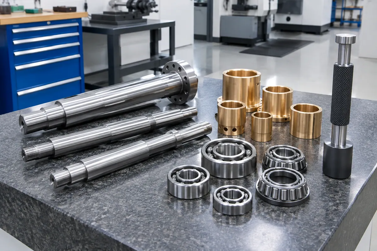
How a material responds to a press fit depends on its elastic modulus, yield strength, and ductility. Steel (200 GPa modulus) deforms much less than aluminum (69 GPa modulus) at the same contact pressure, so the two require different interference values to reach the same retention.
- Brittle metals: Cast iron is prone to hoop-stress cracking if interference exceeds 0.003 in (0.076 mm) on bores under 2 in (50.8 mm) in diameter.
- Soft metals: Pure aluminum, copper, and brass with hardness below 70 HRB yield plastically at the bore wall when radial stress passes their compressive yield (about 95 MPa for pure aluminum). Reduce interference, lengthen the engagement, or pick a stiffer alloy.
- Stainless steels: Grades 303, 304, and 316 work-harden and easily gall during pressing unless lubricated. Heat-treated alloy steels with surface hardness above 60 HRC resist galling and tolerate higher contact pressures.
- Engineering plastics: Nylon, PEEK, and Delrin have a low modulus (1 to 4 GPa) and require larger interference than metals. Because plastics creep under sustained stress, they lose retention over time and belong only in low-load, corrosion-sensitive joints.
Always check interference across the full operating temperature range when joining dissimilar metals. Aluminum alloys like 6061-T6 and 7075-T6 expand at about 23 µm/m·°C, roughly twice the rate of steel at 11 µm/m·°C. If a 50 mm steel shaft sits in an aluminum housing, a 100 °C temperature rise causes about 0.06 mm (0.0024 in) of differential expansion, enough to completely lose a light press fit. Conversely, cooling that assembly increases interference and drives hoop stress toward yield.
Common mistakes and assembly tips
Both excessive and insufficient interference cause premature failure. Too much interference pushes ductile steel or aluminum beyond its elastic limit, permanently deforming the bore so parts cannot be separated without damage, and causes surface asperities to weld and gall. Too little interference allows micro-slip under cyclic loads; this triggers fretting fatigue, which cuts the endurance limit of steel parts by 30% to 60%.
Follow good shop practices during assembly:
- Lubricate pressed joints: Applying lubricant during axial pressing lowers insertion force and prevents galling without significantly cutting final retention, since the lubricant is squeezed out once seated.
- Keep tooling aligned and surfaces clean: Misaligned press tools introduce bending stress into the shaft and score or distort the bore.
- Press on the tight bearing ring only: When mounting a bearing, apply force through a sleeve directly against the face of the ring that has the interference fit. Pressing on the loose ring routes force through the rolling elements and dents the raceways before the bearing ever runs.
Design rules at a glance
| Rule | Value | Note | Source |
|---|---|---|---|
| Maximum contact stress | 70% to 80% of yield strength | Calculated using the Lamé thick-walled cylinder equation to prevent plastic deformation or cracking. | [2] |
| Light press fit interference | 0.0005 to 0.001 in (0.013 to 0.025 mm) | Published guideline for thin-walled or brittle components; confirm with your shop. | [2] |
| Drive fit interference | 0.001 to 0.002 in (0.025 to 0.051 mm) | Assembled with a mallet or light press for parts needing occasional disassembly. | [2] |
| Force fit interference | 0.003 to 0.005 in (0.076 to 0.127 mm) | Requires an arbor or hydraulic press for heavy axial and rotational loads; >0.005 in on large diameters is permanent. | [2] |
| Standard H7/p6 interference | 0.001 to 0.004 in (0.025 to 0.102 mm) | Locational interference fit class; gears typically use 0.001 to 0.004 in. | [1] |
| Bearing race interference | 0.0005 to 0.002 in (0.013 to 0.051 mm) | Prevents race creep and fretting; reduces internal radial clearance. | [2] |
| Maximum interference in cast iron | 0.003 in (0.076 mm) max | Applies to bore diameters under 2 in (50.8 mm) to prevent hoop-stress cracking. | [2] |
| Achievable concentricity | 0.001 to 0.003 in (0.025 to 0.076 mm) | For a shaft centered in a bore by a press fit with proper tolerance control. | [2] |
| Permanent fit pull-out safety factor | 1.5 to 2.5 | Ratio of axial retention force to maximum service pull-out load. | [2] |
| Shrink fit assembly temperatures | 150 to 300 °C (outer) or -196 °C (inner) | Heat outer hub or cool inner shaft in liquid nitrogen to assemble without insertion stress. | [2] |
| Steel-on-steel friction coefficient | 0.1 to 0.2 | Used to calculate axial retention and torque capacity. | [1] |
| Thermal expansion rate (Al vs. steel) | 23 µm/m·°C (Al) vs. 11 µm/m·°C (steel) | Causes a 0.06 mm differential over a 100 °C rise on a 50 mm assembly. | [2] |
Common questions
- Does lubricating a press fit make the joint slip in service?
- No. Applying lubricant during axial pressing lowers the insertion force and prevents galling, especially on stainless steels like 303, 304, and 316. It does not significantly reduce final retention because the lubricant is displaced from the interface once the press is complete.
- When should I choose a shrink fit over an axial press fit?
- Use a shrink fit when you need higher interference than a press can safely push, or when you must avoid axial insertion stress to prevent galling or cracking brittle parts. Heating the outer hub to 150 to 300 °C or cooling the inner shaft to about -196 °C in liquid nitrogen lets the parts slip together with clearance.
- Which bearing ring gets the interference fit?
- Give the interference fit to the ring that rotates relative to the load direction, and give the ring that is stationary relative to the load a looser fit. For a turning shaft under a fixed load direction, press-fit the inner ring onto the shaft. Always apply mounting force only to the face of the ring taking the tight fit so force never passes through the rolling elements.
- Can I use a transition fit to transmit torque?
- No. A transition fit (with a shaft-to-bore difference around -0.001 to +0.001 in) can leave clearance in some mated pairs and does not guarantee retention. Worse, an interface with too little interference will micro-slip under load and cause fretting fatigue, cutting the endurance limit of steel by 30% to 60%. Use transition fits only for location.
- What happens when a steel shaft is press-fit into an aluminum housing that gets hot?
- The fit loosens. Aluminum expands at about 23 µm/m·°C, roughly twice steel's 11 µm/m·°C. On a 50 mm diameter joint, a 100 °C temperature rise grows the aluminum bore 0.06 mm (0.0024 in) more than the steel shaft, which is enough to completely lose a light press fit. Calculate interference at both the minimum and maximum service temperatures.