Milling design guide: pockets, corners, slots and wall limits
Learn how milling works, when to choose it, and how to size corners, walls, threads, slots and keyways so machine shops can build your part.
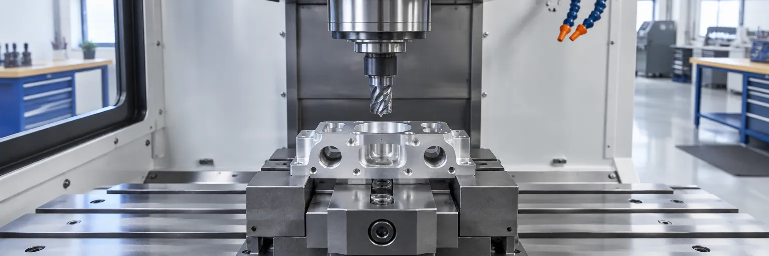
Milling cuts flat faces, pockets, slots and contours using a rotating multi-edge cutter moved across a clamped workpiece. Nearly all production milling today is CNC milling, where the machine follows programmed toolpaths. Designing a part that mills cleanly means accounting for the round, slender shape of the cutter and the forces it puts on your material.
What milling is and when to use it
Milling uses a rotating cutter with multiple cutting edges to remove material from a workpiece held in a vise, fixture or directly on the machine table. Almost all production milling is CNC milling, and the different machine variants vary by how many directions the spindle can approach the part.
Choose milling for parts whose features are mostly flat, stepped or pocketed and reachable from one or a few directions. Typical milled parts include brackets, housings, plates, manifolds and fixtures. If a part is round about an axis, turn it instead, or combine turning and milling when a part has both kinds of geometry.
Milling trades cutting time for geometric flexibility. It works best for moderate quantities and materials that cut readily, such as aluminum alloys.
Core design rules from cutter geometry
Every design rule for milling comes directly from the shape and reach of the cutter. The figures below are published design guidance from a manufacturing service (Hubs), not rules every shop follows, so always confirm limits with your shop.
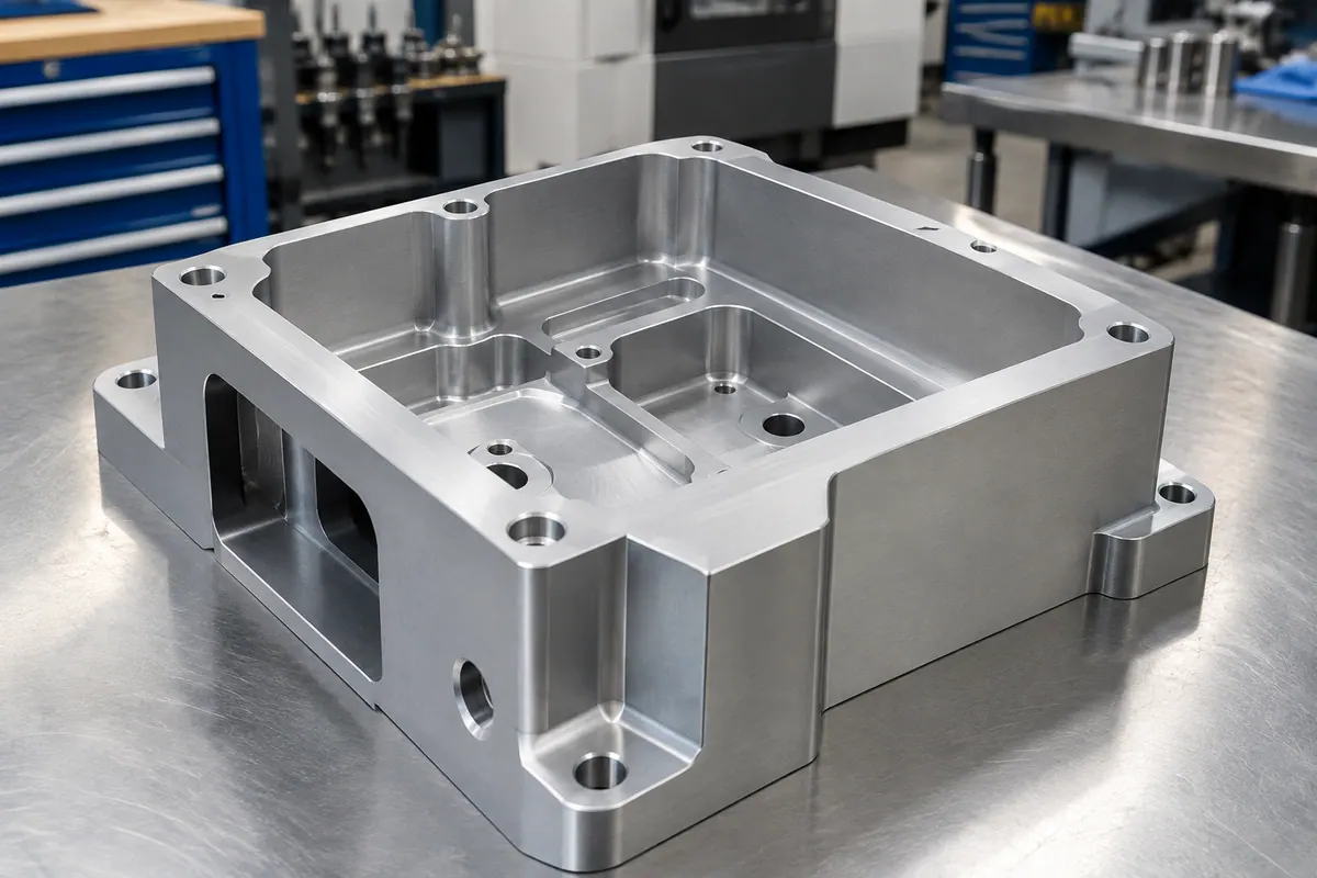
- Inside corners and floor radii: Because the cutter is round, every vertical inside corner gets the radius of the tool. On pocket floors, specify a floor radius of 0.5 mm (0.020 in), 1 mm (0.039 in) or none.
- Deep, narrow features: A long, thin cutter deflects and chatters under cutting load. Do not design deep cuts that require small-diameter end mills.
- Wall thickness and height: Keep thin standing features under four times their width. In metal, walls thinner than 0.8 mm (0.031 in) vibrate and deflect, so a thin wall that looks fine in CAD can fail during the cut.
- Text and markings: Prefer engraved text over embossed text so the shop does not have to mill away the surrounding surface.
Undercuts, slots, dovetails and keyways
Because the cutter approaches from the spindle, any undercut requires dedicated tooling and extra passes. Keep undercuts shallow and size them to standard cutters.
- T-slots: Milling a T-slot takes two cutters. The shop first cuts a plain groove of the throat width to about 1/16 in (1.59 mm) short of the combined throat and head-space depth using a side or end mill, then cuts the head space with a standard T-slot cutter sized to the bolt diameter.
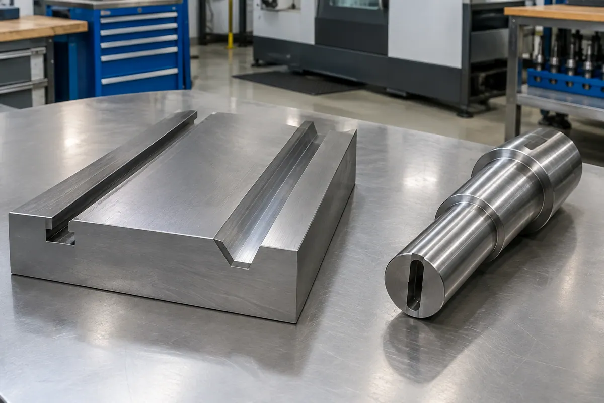
- Dovetails: Shops rough the tongue or groove with a side milling cutter and finish the angled sides and base with a single-angle cutter of 45, 50, 55 or 60 degrees.
- Narrow slots: Slitting saws cut deep, narrow slots and part stock on horizontal mills. Standard metal slitting saws range from 0.03125 in (0.794 mm) to 3/16 in (4.76 mm) wide.
- Shaft keyways: Standard square-end and round-end machine keys have a width about 1/4 of the shaft diameter, a flat key thickness about 1/6 of the shaft diameter, and a minimum length of 1.5 times the shaft diameter. Keyway depth is half the key width for a square key or half the key thickness for a flat key. Square-end keyways are cut with a plain or side cutter, round-end keyways with an end mill matching the key width across several passes to remove tool spring, and Woodruff keyways with a matching number Woodruff cutter.
Holes, threads and small features
Small features drive up cost and tooling risk in milled parts. Published service guidance (Hubs) flags several practical limits to watch out for when sizing holes and fasteners.
- Small holes and features: Features and holes smaller than 2.5 mm (0.098 in) require micro-machining rather than standard milling tooling.
- Thread size: Avoid threads smaller than M6 where possible, as small taps break easily.
- Thread depth: Keep threaded hole engagement to at most 1.5 times the thread diameter. Deeper engagement adds machining time and cost without adding strength.
Surface finish, tolerances and shop practice
In ordinary production milling, as-produced surface roughness typically falls between 0.8 um Ra (32 uin) and 6.3 um Ra (250 uin). Where a part lands in this range depends on the material, cutter and machine settings. For general linear, angular and geometrical tolerances on drawings without individual callouts, ISO 2768-1 and ISO 2768-2 apply.
How a shop sets up and cuts your part directly affects accuracy and finish:
- Roughing vs. finishing: Shops rough at a moderate spindle speed and heavy feed with a coarse-tooth cutter to remove metal quickly, then finish at a higher speed and lighter feed with a finer-tooth cutter.
- Cutter selection: For flat faces, a fly cutter ground from a single tool bit produces a high-quality finish on aluminum and soft nonferrous metals, and works well for special forms on small runs. Broad surfaces are face milled with a cutter just wide enough to span the work in one pass.
- Coolants and dry cutting: Water-based coolant is used for roughing to carry away heat, and lubricating oil is used for finishing to protect the surface finish. Plastics and cast iron are almost always milled dry.
- Workholding and rigidity: Frail or thin parts that cannot be clamped without springing cannot take heavy cuts. Long, slender parts held between centers require a jackscrew beneath the cut to prevent deflection.
Design rules at a glance
| Rule | Value | Note | Source |
|---|---|---|---|
| Minimum metal wall thickness | 0.8 mm (0.031 in) | Published service guidance; thinner walls vibrate and deflect under cut. | [1] |
| Maximum standing feature height-to-width ratio | 4:1 | Published service guidance for thin standing features. | [1] |
| Pocket floor radius | 0.5 mm (0.020 in), 1 mm (0.039 in), or none | Published service guidance for standard cutter floor radii. | [1] |
| Minimum standard feature and hole size | 2.5 mm (0.098 in) | Published service guidance; smaller features require micro-machining. | [1] |
| Minimum recommended thread size | M6 | Published service guidance; smaller taps are prone to breaking. | [1] |
| Maximum effective thread engagement | 1.5 x diameter | Published service guidance; deeper threads add cost without adding strength. | [1] |
| As-produced surface roughness (Ra) | 0.8 to 6.3 um (32 to 250 uin) | Average range in ordinary roughing to finishing production. | [3] |
| Slitting saw slot width | 0.03125 to 0.1875 in (0.794 to 4.76 mm) | Standard metal slitting saw widths (1/32 to 3/16 in) for deep narrow slots. | [2] |
| Standard dovetail cutter angles | 45, 50, 55, or 60 degrees | Usual single-angle cutters used after roughing with a side cutter. | [2] |
| Standard shaft key proportions | Width 1/4 D; flat thickness 1/6 D; min length 1.5 D | Proportioned to shaft diameter (D) for square-end and round-end keys. | [2] |
| HSS face mill feed per tooth (aluminum) | 0.007 to 0.022 in/tooth (0.178 to 0.559 mm/tooth) | Used with spindle RPM and tooth count to calculate table feed rate. | [2] |
| HSS face mill feed per tooth (free-machining steel) | 0.003 to 0.012 in/tooth (0.076 to 0.305 mm/tooth) | Used with spindle RPM and tooth count to calculate table feed rate. | [2] |
Common questions
- When should I choose milling instead of turning?
- Use milling when your part is mostly flat, stepped or pocketed and approached from one or a few directions, such as a bracket, manifold, plate or housing. Use turning for parts that are round about an axis, or combine both processes when a part has both round and prismatic features.
- Why do thin walls and deep pockets cause trouble in milling?
- Cutting force increases with feed and depth of cut. Long, thin end mills deflect and chatter in deep features, and metal walls thinner than 0.8 mm (0.031 in) or taller than four times their width vibrate and spring away from the cutter.
- How should I size undercuts like T-slots and dovetails?
- Keep undercuts shallow and size them to standard cutters so the shop does not need custom tooling. Size T-slots to standard bolt diameters (milled in two steps with a groove cutter and a T-slot cutter) and design dovetails around standard 45, 50, 55 or 60 degree angle cutters.
- How deep should I make tapped holes in a milled part?
- Limit thread engagement to 1.5 times the thread diameter and stay at or above M6 where possible. Tapping deeper than 1.5 diameters increases cycle time and tap breakage risk without making the joint stronger.
- What surface finish can I expect straight off a milling machine?
- Ordinary production milling produces a surface roughness between 0.8 um Ra (32 uin) and 6.3 um Ra (250 uin), depending on the material, cutter and feed. On flat aluminum and soft nonferrous faces, a shop can also use a single-point fly cutter for a high-quality finish.