Metal binder jetting design guide: tolerances, walls and shrinkage
Learn how metal binder jetting works, when to use it, and how to design parts for green-state handling and furnace sintering.
Metal binder jetting prints complex metal parts in batches without printing supports or thermal warping. Because printed green parts are fragile and shrink in a sintering furnace, your geometry must survive both handling and high heat. This guide covers material choices, feature limits, tolerances, and what to watch out for when ordering parts.
What metal binder jetting is
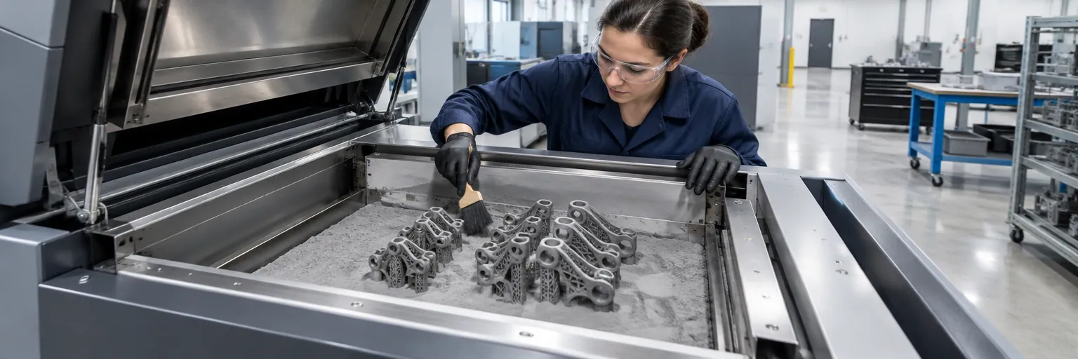
Metal binder jetting is a two-stage additive process. First, inkjet nozzles deposit a liquid polymer-and-wax binder onto thin layers of metal powder at room temperature. This binds the particles into a fragile shape called a green part.
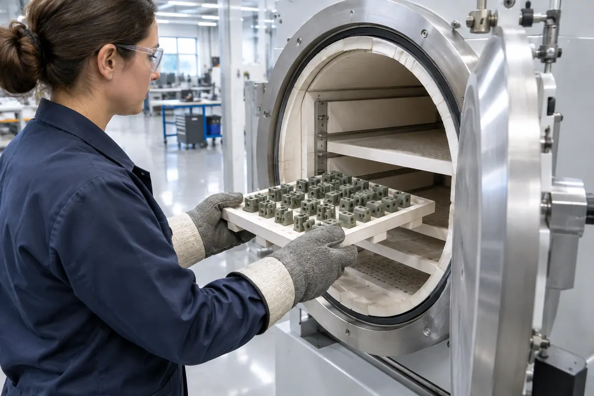
Second, the green part goes into an industrial furnace to become fully metal, either by sintering or by infiltrating with bronze. In the standard sintering route, the printer scales the green part up by about 20 percent. The furnace burns off the binder and sinters the metal particles together, shrinking the part down to its target size.
Typical machines spread powder in layers 35 to 50 microns thick per pass. One manufacturing service prints layers at 0.004 in (0.10 mm) and typically orients parts in the lowest Z direction to minimize build height.
When to use it
Choose metal binder jetting for batches of small, complex metal parts where unit cost matters more than full material density. Because the printing step happens at room temperature, parts do not warp or build up internal thermal stress. No printing supports are needed, so shops can pack the entire build volume to run batches economically.
A typical build box is 400 by 250 by 250 mm (about 15.75 by 9.84 by 9.84 in). Because the green part shrinks by about 20 percent during sintering, the effective maximum part size is about 20 percent smaller than the build box.
If you need a denser, stronger part and can pay a higher price, use laser powder bed fusion instead. Another alternative is metal extrusion, which uses a similar furnace sintering step but prints at lower resolution.
Suitable materials
Material suitability depends on how well the powder sinters in the furnace. Note that general material ratings are advisory; always check what specific alloys your shop stocks.
- Stainless steels: Austenitic grades like 316L and precipitation-hardening grades like 17-4 PH are rated excellent and are the main powders used.
- Tool steels and superalloys: Cold-work tool steels and nickel superalloys like Inconel 625 are rated good for printing and sintering.
- Copper and low-carbon steel: Pure copper is rated fair because shrinkage and conductivity need careful control. Low-carbon and low-alloy steels are also rated fair and require carbon control.
- Aluminum and titanium: Aluminum is rated poor because its surface oxide film prevents sintering. Commercially pure titanium is also rated poor because it is reactive and needs a special furnace atmosphere.
Design rules and feature limits
Green parts are fragile before sintering, and parts can sag in the furnace. Published limits come from manufacturing services like Hubs and Xometry; treat them as baseline guidance and confirm exact capabilities with your shop.
- Wall thickness: Keep walls at least 1 mm (0.039 in) thick so the green part does not break during handling.
- Feature size: Make isolated features at least 2 mm (0.079 in) wide. One service recommends a general feature minimum of 0.04 in (1 mm) and requires thickening any feature below 0.03 in (0.75 mm).
- Surface detail: Fine surface details can go down to 0.1 mm (0.004 in), which is set by the binder droplet size.
- Holes: Design holes at least 1 mm (0.039 in) in diameter. Use a teardrop shape for holes that run off the build axis.
- Overhangs and edges: Keep horizontal unsupported edges to at most 20 mm (0.787 in). Add chamfers under unsupported edges, add ribs to tall thin features, and use an insert instead of a printed pin.
Shrinkage, tolerances and surface finish
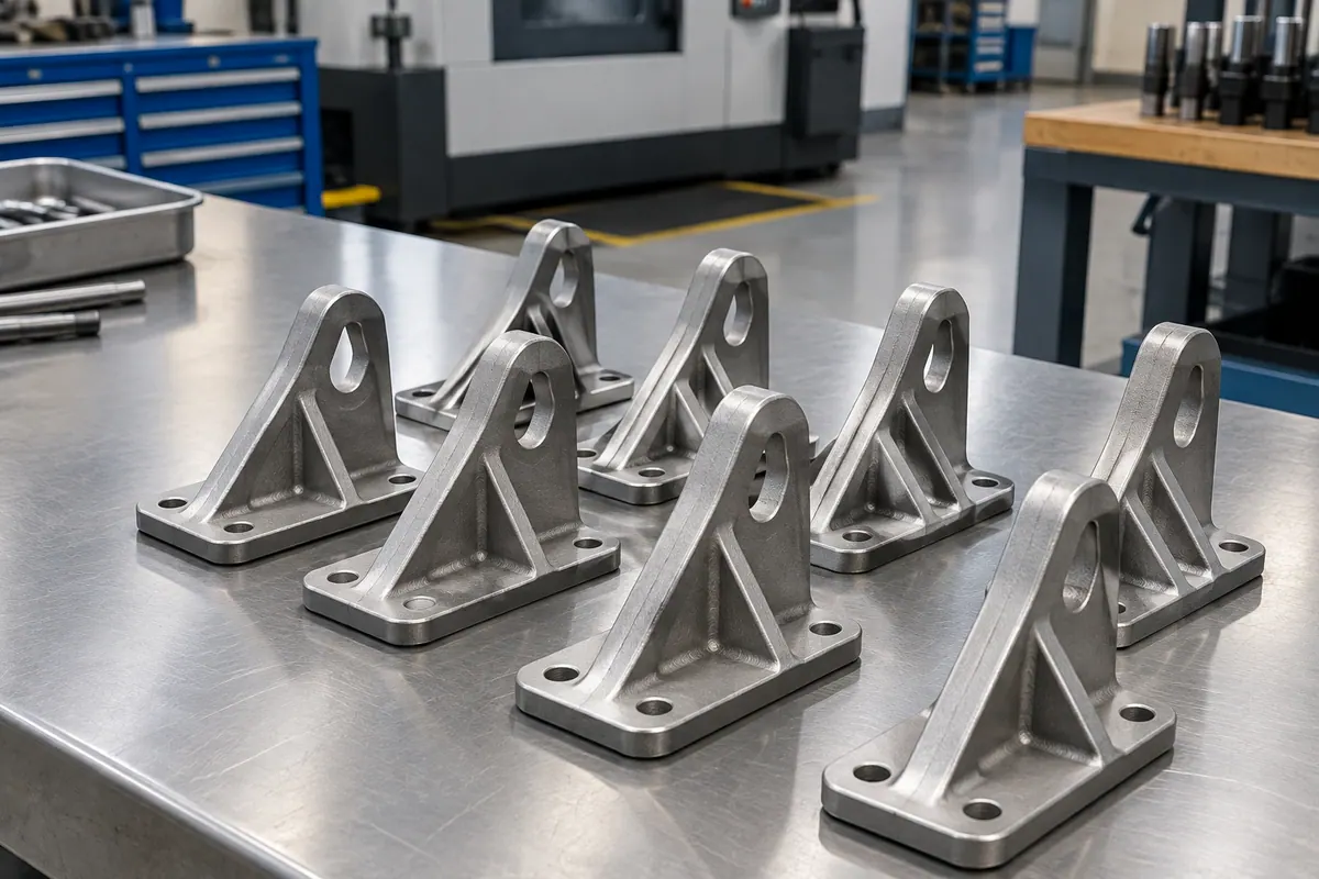
Furnace post-processing is required for every part, and shrinkage happens in stages. During sintering, the green part undergoes about 20 percent linear shrinkage, which the printer compensates for by scaling the print up. However, sintering shrinkage is non-homogeneous and hard to predict.
Published tolerances and shrinkage figures vary by service. In one service's guidance for a typical machine, dimensional tolerance is ±0.2 mm (±0.008 in) on a first-time design. After running several trial prints to calibrate the CAD model for shrinkage, tolerance improves to ±0.1 mm (±0.004 in) with excellent repeatability. Another service reports 0.8 to 2.5 percent overall shrinkage on delivered parts after processing, and up to 5 percent shrinkage on internal geometries like slots and holes (before secondary finishing).
For surface roughness, one publisher lists a typical as-sintered finish of about 6 microns Ra. Another service lists an as-printed finish of 120 to 315 microinches Ra (about 3.0 to 8.0 microns Ra). Always confirm tolerances and finishes with your supplier.
What to watch out for
Account for the physical limits of sintered powder metal before finalizing your design and requesting quotes.
- Porosity and fatigue: Sintered binder-jetted parts always retain 0.2 to 2 percent internal porosity. This barely affects tensile strength, but it reduces fatigue strength significantly. Do not use this process for cyclically loaded parts.
- Furnace supports: Even though printing requires no supports, green parts may still need support structures inside the sintering furnace to prevent sagging.
- Threads and precision features: Modeled threads and tight features may have limited function as printed. Plan to machine or tap critical features after sintering.
- Trapped tumbling media: If you order a tumble-polished finish, crushed walnut media can get lodged inside thin gaps or recessed text.
- Calibration runs: If you need tight tolerances on a new part, build time and budget into your schedule for trial prints to dial in the shrinkage compensation.
Design rules at a glance
| Rule | Value | Note | Source |
|---|---|---|---|
| Typical build envelope | 400 x 250 x 250 mm (15.75 x 9.84 x 9.84 in) | Before sintering; effective part size is about 20% smaller after sintering | [2] |
| Layer thickness | 35 to 50 um; or 0.004 in (0.10 mm) | 35 to 50 um on typical machines; 0.004 in on Xometry machines | [1] |
| Minimum wall thickness | 1 mm (0.039 in) | Thicker walls reduce breakage of fragile green parts | [2] |
| Minimum isolated feature size | 2 mm (0.079 in) | As-designed isolated feature; Xometry recommends 0.04 in (1 mm) minimum and thickening below 0.03 in (0.75 mm) | [2] |
| Minimum surface detail | 0.1 mm (0.004 in) | Depends on binder droplet size | [2] |
| Minimum hole diameter | 1 mm (0.039 in) | As-designed hole; use teardrop shapes off the build axis | [2] |
| Maximum horizontal unsupported edge | 20 mm (0.787 in) | No printing supports needed, but sintering support may be required | [2] |
| Dimensional tolerance (first-time design) | ±0.2 mm (±0.008 in) | Typical machine before trial print calibration | [2] |
| Dimensional tolerance (calibrated) | ±0.1 mm (±0.004 in) | After trial prints to calibrate non-homogeneous sintering shrinkage | [2] |
| Green part sintering shrinkage | About 20% | Linear shrinkage in the furnace; compensated by printing the part larger | [2] |
| Delivered part shrinkage (Xometry default) | 0.8% to 2.5% overall; up to 5% on internal features | Applies to slots, holes, and overall geometry before secondary finishing | [3] |
| Internal porosity | 0.2% to 2.0% | Retained in sintered part; lowers fatigue strength | [2] |
| Surface roughness | 6 um Ra; or 120 to 315 uin Ra (3.0 to 8.0 um Ra) | 6 um Ra as sintered (Hubs); 120 to 315 uin Ra as printed (Xometry) | [1] |
Common questions
- Does metal binder jetting require support structures?
- No supports are needed during printing because the process runs at room temperature and the surrounding powder bed supports the part. However, parts may still need support structures inside the furnace to prevent sagging during sintering.
- Why are binder-jetted parts a poor fit for fatigue applications?
- Sintered binder-jetted parts always retain 0.2 to 2 percent internal porosity. While this porosity has little effect on tensile strength, it can cause fatigue strength to drop significantly under cyclic loads.
- How much do metal binder-jetted parts shrink, and how does that affect tolerances?
- Green parts shrink linearly by about 20 percent in the furnace, so printers scale the model up to compensate. Because shrinkage is non-homogeneous, one service reports a typical tolerance of ±0.2 mm (±0.008 in) on a first print, improving to ±0.1 mm (±0.004 in) after trial prints calibrate the model. Another service notes 0.8 to 2.5 percent overall shrinkage on delivered parts and up to 5 percent on internal holes and slots.
- Can I print functional threads with metal binder jetting?
- Modeled threads and other precision features may have limited functionality as printed due to shrinkage and surface roughness. For reliable threads, use an insert or tap the hole after sintering.
- Which metals work best for metal binder jetting?
- Austenitic stainless steels like 316L and precipitation-hardening grades like 17-4 PH are rated excellent and are the standard powders. Cold-work tool steels and nickel superalloys like Inconel 625 are rated good. Aluminum and commercially pure titanium are rated poor because of oxide films and reactivity during sintering.