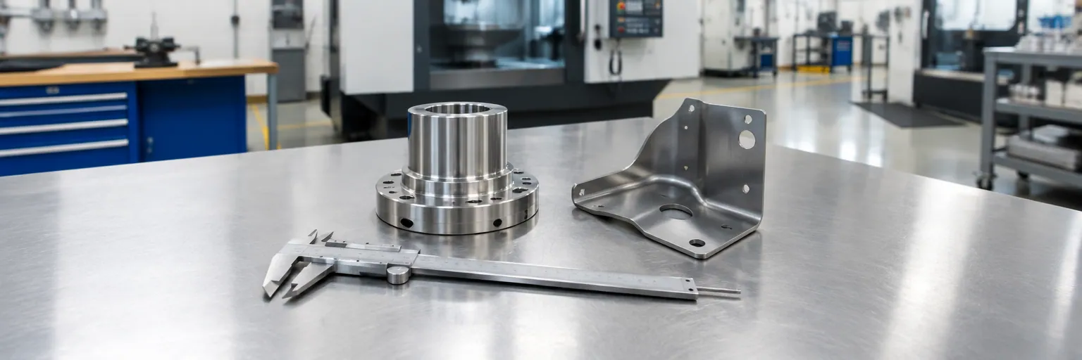
ISO 2768 general tolerances: classes, callouts and when to use
Learn how ISO 2768 general tolerances work, how the चार classes scale with part size, how to call them out, and when to tolerance features individually.
ISO 2768 sets default tolerances for dimensions on a drawing that do not have an individual tolerance of their own. Naming the standard and a class once in your title block keeps drawings clean while telling the shop the baseline workshop accuracy you expect. You then apply explicit tolerances only to the features that matter for fit or function.
What ISO 2768 is and what it covers
ISO 2768 is a two-part standard first published in 1989 for general tolerances on engineering drawings. It defines the permissible deviations for features that carry no explicit tolerance on the drawing face.
Part 1 (ISO 2768-1) covers linear and angular dimensions across three tables and includes an annex explaining the concept behind general tolerancing. Confirmed as current in 2022, it remains in active use while awaiting a future revised ISO 2768.
Part 2 (ISO 2768-2) covered general geometrical tolerances such as straightness, flatness, and perpendicularity across three classes. ISO has withdrawn Part 2 in favor of ISO 22081. Some drawings still invoke Part 2, though doing so relies on a superseded document; current practice under ISO GPS rules uses ISO 22081 alongside the fundamental principles of ISO 8015.
When to use ISO 2768 (and when not to)
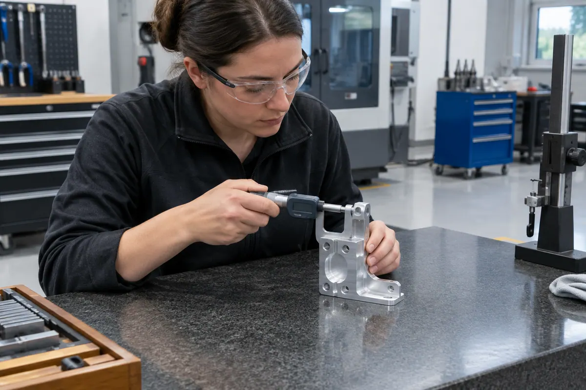
Use ISO 2768-1 for parts produced by metal removal (such as CNC machining) or formed from sheet metal where most dimensions are ordinary and only a few require tight control. Many machining services treat it as their baseline default; a typical standard machining tolerance of plus or minus 0.125 mm (0.0049 in) corresponds roughly to class m for mid-size features.
Do not rely on ISO 2768 for every manufacturing process or drawing framework:
- Castings have their own general tolerance standard, ISO 8062-3.
- Molded plastic parts are covered by ISO 20457.
- Drawings prepared under ASME Y14.5 belong to a different standards family and state their general tolerances differently.
How the four tolerance classes work
ISO 2768-1 defines four tolerance classes to match different workshop accuracies:
- f (fine)
- m (medium)
- c (coarse)
- v (very coarse)
In every class, the permissible deviation scales with the nominal size of the feature. The classes tighten sharply on small features and open up as dimensions grow. For example, in class m, a dimension in the 6 to 30 mm (0.236 to 1.181 in) range is held to plus or minus 0.1 mm (0.0039 in), while a dimension from 120 to 400 mm (4.724 to 15.748 in) is held to plus or minus 0.5 mm (0.0197 in).
Always consult the official standard tables rather than working from memory, and pick a class that fits your manufacturing process. Calling out a fine (f) class on a large fabricated or sheet-metal part asks for more accuracy than the shop's process will deliver.
How to call out ISO 2768 on a drawing
To apply the standard, add a single note in or near the drawing title block stating the standard and the chosen Part 1 class. For a medium-class linear and angular default, write:
- ISO 2768-m
Once that note is in the title block, every linear and angular dimension without an explicit tolerance inherits its permissible deviation from the ISO 2768-1 tables. If your drawing also sets general geometrical tolerances, current ISO practice specifies them using ISO 22081 rather than the withdrawn Part 2.
When to tolerance a feature on its own
General tolerances are only for non-critical dimensions. Whenever a feature mates with another part, locates an assembly, or drives function, give it an individual tolerance directly on the drawing view.
An explicit tolerance on a dimension overrides the title-block general tolerance for that feature. Do not lean on ISO 2768 to control critical interfaces: use ISO 286 limits and fits for mating shafts and holes, and apply explicit geometrical tolerances under ISO 1101 where form, orientation, or position matters to how the part works.
Common mistakes to avoid
Keep these limitations in mind before releasing a drawing:
- Treating the standard as a shop capability guarantee: A general tolerance is a drawing default, not proof of what a given shop holds. Every manufacturing service publishes its own capability limits, so always confirm with your shop.
- Over-tolerancing via the title block: Specifying a class your shop cannot hold turns every ordinary, untoleranced feature on the part into a quality nonconformance.
- Forgetting small-feature tightness: Because the tables tighten sharply at small basic sizes, check that tiny non-critical features do not accidentally get an unnecessarily tight limit.
- Invoking withdrawn standards unawares: Remember that Part 2 is withdrawn in favor of ISO 22081.
Design rules at a glance
| Rule | Value | Note | Source |
|---|---|---|---|
| Part 1 tolerance classes | f (fine), m (medium), c (coarse), v (very coarse) | Four classes for linear and angular dimensions on metal-removal and sheet-metal parts. | [1] |
| Typical title-block callout (medium) | ISO 2768-m | Applies class m permissible deviations to all untoleranced linear and angular dimensions. | [1] |
| Example linear deviation (6 to 30 mm, class f) | +/- 0.05 mm (0.0020 in) | Fine class example from the overview for mid-small features. | [1] |
| Example linear deviation (6 to 30 mm, class m) | +/- 0.1 mm (0.0039 in) | Medium class example from the overview for mid-small features. | [1] |
| Example linear deviation (120 to 400 mm, class m) | +/- 0.5 mm (0.0197 in) | Medium class example showing how permissible deviation increases with size. | [1] |
| Typical machining service default | +/- 0.125 mm (0.0049 in) | Published service guidance corresponding roughly to class m for mid-size features; confirm with your shop. | [1] |
Common questions
- Does ISO 2768 apply to 3D models or only 2D drawings?
- ISO 2768 is written for engineering drawings, where a single note in the title block governs linear and angular dimensions that have no individual tolerance indication.
- Can I use ISO 2768 for injection-molded plastic or cast metal parts?
- No. ISO 2768-1 is written for parts made by metal removal or formed from sheet metal. Castings use ISO 8062-3 and molded plastic parts use ISO 20457.
- Is ISO 2768-2 still active for geometrical tolerances?
- No. ISO has withdrawn ISO 2768-2 in favor of ISO 22081. While some legacy drawings still call out Part 2, current practice under ISO GPS rules uses ISO 22081.
- What happens if I put an explicit tolerance on a dimension when ISO 2768 is in the title block?
- The explicit tolerance applies. ISO 2768 tables only govern dimensions that have no individual tolerance indication of their own.
- Does calling out ISO 2768-f guarantee my shop will hold fine tolerances?
- No. A general tolerance states what the drawing requires, not what a shop's equipment can hold. Always check your shop's published tolerances and confirm capability before ordering.