Injection molding design guide: walls, draft, ribs and tooling
Design rules for injection molded plastic parts: wall thickness, draft angles, ribs, bosses, corners, undercuts, threads and tooling cost drivers.
Injection molding forms plastic parts by forcing molten polymer into a clamped mold under pressure and cooling it to shape. Once your quantity pays for the steel or aluminum tool, no other process makes repeatable plastic parts as cheaply at volumes in the thousands to millions. Because modifying a finished mold is very expensive, you need to build uniform walls, proper draft and clean parting lines into your part from the start.
What it is and materials
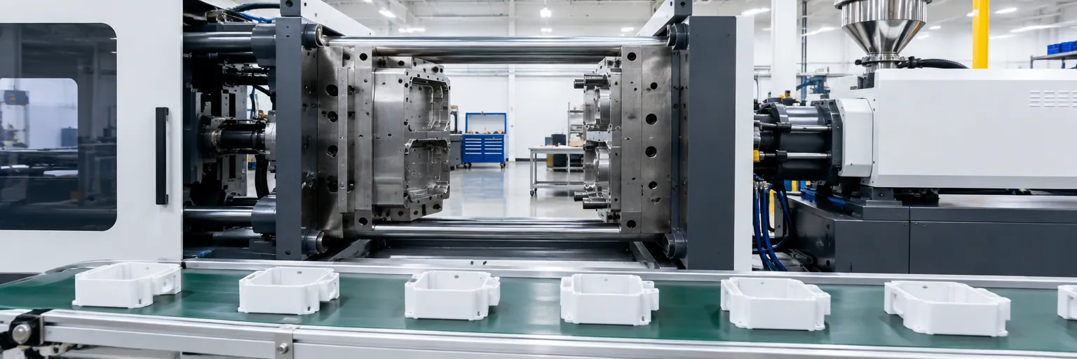
An injection molding machine melts plastic pellets in a heated screw barrel and injects the melt into a closed mold. Cooling takes up about 70 percent of the total cycle time before the mold opens and ejects the part.
It is the primary process for thermoplastics at volume. Common resins have distinct molding behaviors:
- Excellent suitability: ABS, polycarbonate (PC), nylon (polyamide), acetal, polypropylene (PP), polyethylene (PE) and polystyrene. Polyethylene molds easily and cheaply, though high shrinkage requires uniform walls. General-purpose polystyrene flows fast but is brittle.
- Good suitability: PEEK and PPS (both need high melt and mold temperatures), acrylic (molds clear parts if dried well and kept low-stress to prevent crazing), thermoplastic polyesters like PBT and PET (must be dried), and elastomers (TPU molds like a thermoplastic; rubber is molded and vulcanized in the tool).
- Fair suitability: Rigid PVC is heat-sensitive and corrodes unprotected steel, requiring stainless-steel molds and careful temperature control. Thermosets rate fair because they cannot be re-melted once cured and are usually compression or transfer molded.
- Unsuitable: PTFE cannot be melt-processed and is compression molded and sintered instead.
Wall thickness and corners
Keep wall thickness constant across the entire part. Non-uniform walls cool and shrink at different rates, building internal stresses that permanently warp the part. Thick sections also cause sink marks when the core solidifies slower than the outer skin and pulls the surface inward. Conversely, very thin walls can trap air and stop the melt from filling the cavity, causing a short shot.
If you must change wall thickness, blend the transition with a chamfer or fillet over a length at least 3 times the thickness difference. Hollow out thick solid blocks to match your nominal wall and use ribs to restore stiffness.
One manufacturing service publishes recommended nominal wall ranges by resin:
- ABS: 0.045 to 0.140 in
- Polycarbonate: 0.040 to 0.150 in
- Nylon: 0.030 to 0.115 in
- Polypropylene: 0.035 to 0.150 in
- Acetal: 0.030 to 0.120 in
- Polyethylene: 0.030 to 0.200 in
Round all corners so material flows smoothly and stress does not concentrate. Give internal corners a radius of at least 0.5 times the wall thickness, and external corners a radius equal to the internal radius plus the wall thickness (1.5 times the wall). This keeps the wall thickness constant around the turn. Also remember that a CNC-milled aluminum mold naturally leaves radii on inside corners that look sharp in CAD.
Draft angles and surface texture
Every vertical face on both the cavity and core sides needs a draft angle so the part releases cleanly. As plastic cools, it shrinks and grips the core. Without taper, ejection causes drag marks, scratches the part, wears the tool, warps the part or jams production completely. A part that releases easily also needs fewer ejector pins, freeing space inside the core for cooling channels that speed up the cycle.
Add draft early in your CAD model, even when 3D printing or CNC machining prototypes, so you do not have to rebuild the geometry later. Check which reference face you draft from so the taper does not ruin the fit of mating parts.
Published draft guidelines vary slightly by service, so confirm requirements with your molder:
- General untextured walls: 0.5 degrees is the absolute floor on any vertical face, while 2 degrees is standard for most situations. Protolabs recommends 3 degrees on mold shut-offs.
- Tall features and deep pockets: Vacuum and friction grow with depth. Hubs recommends increasing draft up to 5 degrees on tall features by adding 1 degree for every 25 mm (1 in) of height above 50 mm (2 in), or generally adding 1 to 2 degrees per inch (25.4 mm) of cavity depth.
- By material (Hubs recommended draft / minimum in ideal conditions): Nylon 1 degree (0 degrees minimum); polyethylene and PVC 1.5 degrees (0.5 degrees minimum); polypropylene 2 degrees (1 degree minimum); polycarbonate 2 degrees (1.5 degrees minimum). High-shrink, brittle or abrasive resins need more draft than soft, ductile or self-lubricating ones.
- Textured surfaces: Texture creates micro-undercuts that grip the mold. Both Hubs and Protolabs state that a light bead-blast texture (such as PM-T1) needs at least 3 degrees, and a heavy texture (PM-T2) needs 5 degrees or more. More broadly, Hubs advises 1 to 5 degrees for light textures and 5 to 12 degrees or more for complex leather-like textures.
Ribs, bosses and other features
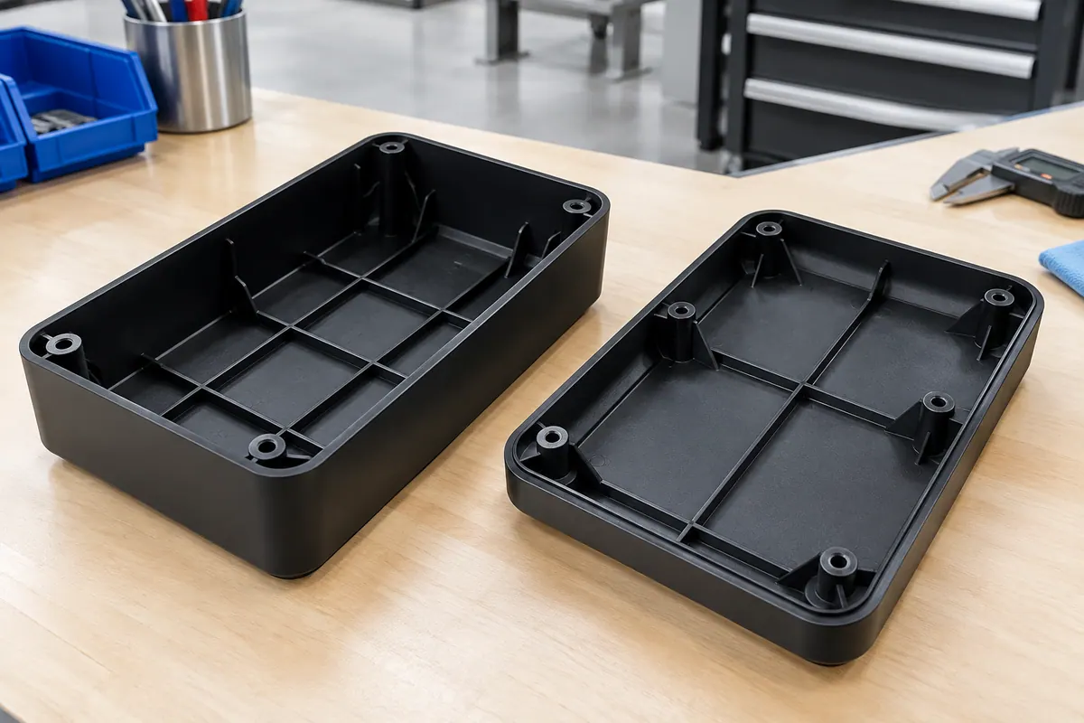
Use several thin ribs rather than one thick rib to stiffen a wall without causing sink marks on the opposite cosmetic face. Manufacturing services publish slightly different rib proportions:
- Hubs guidelines: Keep rib thickness at 0.5 times the main wall (maximum), rib height under 3 times the rib thickness, base fillet radius at least 0.25 times the rib thickness, spacing between ribs at least 4 rib thicknesses, and rib draft at 0.25 to 0.5 degrees. Check that draft does not thin the top of the rib below minimum wall limits.
- Xometry guidelines: Allow rib thickness up to 60 percent of the wall (40 percent on glossy parts), base radius of 0.5 to 1 wall thickness, spacing of 2.5 to 3 wall thicknesses, and 0.5 to 1.5 degrees of draft.
For fastening bosses, set the outer diameter to twice the nominal screw or insert diameter, and the inner hole to the screw's core diameter. Extend the hole all the way to the base wall level to keep section thickness uniform, and chamfer the mouth. Never merge a boss directly into a main wall; stand it off and connect it with ribs, rounding the base of every vertical feature.
Avoid molding threads directly onto a part because thread teeth act as undercuts that raise mold cost. Instead, use self-tapping screws in a boss or install metal threaded inserts after molding (thermally or ultrasonically) or in-mold. If you must mold a thread, use a coarse trapezoidal or buttress profile with a pitch over 0.8 mm (0.031 in, or 32 tpi), add 0.8 mm (0.031 in) of thread relief at the ends, and place external threads along the parting line.
For specialized features, follow these published guidelines:
- Living hinges: Mold in polypropylene or polyethylene (or nylon for engineering parts) at 0.20 to 0.35 mm (0.008 to 0.014 in) thick. Keep individual hinge segments at most 150 mm (5.9 in) long, make the shoulders match the main wall thickness, and use large fillets.
- Crush ribs: In press-fit holes for shafts or bearings, add three crush ribs for alignment with a 2 mm (0.079 in) height and radius and at least 0.25 mm (0.010 in) of interference. Because mold contact is small, crush ribs do not need draft.
- Molded text: Emboss (raise) text rather than engraving it so it is cheaper to CNC mill into the tool. Make letters at least 0.5 mm (0.020 in) high in a bold, rounded font of at least 20 points, aligned perpendicular to the parting line.
Undercuts and parting lines
A straight-pull two-part mold is the cheapest tool to build and maintain. Undercuts prevent a part from ejecting straight out of the mold and always increase cost and complexity.
Design undercuts out whenever you can:
- Move the parting line: Relocate the mold parting line so it intersects an external undercut, and adjust your draft angles to match the new line.
- Use shut-offs: Remove material beneath an internal snap-fit, side hole or handle so a core from the opposite mold half can pass through and form the feature without a side pull. Draft cantilever snap-fits on their vertical walls and make them thicker than 0.5 times the wall.
- Use a stripping undercut (bumpoff): On flexible, unreinforced plastics like polypropylene, HDPE or nylon, a feature can deform over the mold during ejection if the undercut depth is at most 5 percent of the feature diameter, has a 30 to 45 degree lead angle, and sits away from stiffening corners and ribs. Never use stripping undercuts on fiber-reinforced plastics.
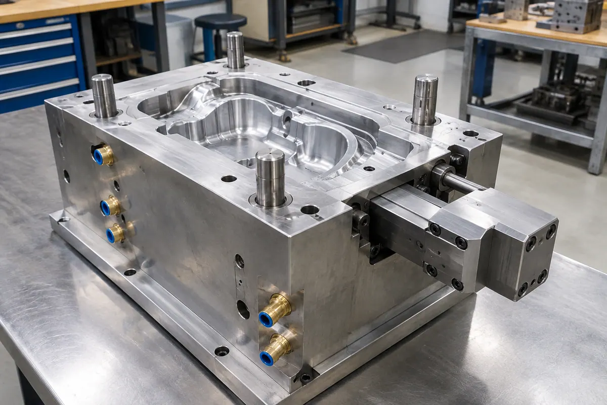
When an undercut cannot be removed, the tool needs a sliding side-action core. Side-actions add roughly 15 to 30 percent to tooling cost. Place the feature on the outside of the part, design the action to move perpendicular to the mold opening direction (angled actions cost more and take longer), and draft the feature in the direction of the slide. As an example of service limits, one vendor caps side-action cores at under 8.419 in wide, 2.377 in high and 2.875 in of pull.
Tolerances, defects and tooling cost
Tolerances depend on resin shrinkage and process control; high-shrink polypropylene is harder to hold tight than polycarbonate. ISO 20457 governs dimensional and geometrical tolerances and acceptance conditions for molded plastic parts. Manufacturing services also publish their own capabilities:
- Hubs lists ±0.25 mm (±0.010 in) as a typical general tolerance, ±0.125 mm (±0.005 in) as feasible, and ±0.025 mm (±0.001 in) as an extreme limit at drastically higher cost.
- Protolabs states mold machining tolerances of ±0.003 in.
- Xometry publishes ±0.005 in plus ±0.002 in per inch, with part-to-part repeatability under ±0.004 in, and an envelope up to 29.6 in on the second dimension with 4 in of depth from the parting line (8 in if the parting line splits the part).
Treat any published number as that vendor's guideline for its own equipment, not a universal law. Tight tolerances require making, sampling and grooming the tool.
To keep tooling and part costs down, watch how your design drives the process:
- Cycle time and cavities: Thinning a wall from 3 mm (0.118 in) to 2 mm (0.079 in) can cut cycle time by 50 to 75 percent. Fitting six to eight small parts into a multi-cavity mold cuts total production time by about 80 percent.
- Low-volume trade-offs: Below about 1,000 parts, drilling a side hole after molding can cost less than paying for a side-action core. Below about 10,000 parts, machining a tight press-fit feature in a secondary operation is often cheaper than paying to hold tight molded tolerances. For 1 to 1,000 parts, consider urethane casting or laser-sintered nylon before committing to hard tooling.
- Cosmetics and knit lines: Where two melt fronts meet around a hole or abrupt transition, they form a discolored, weaker knit line. High-grade hand-polished mold finishes require harder, costlier tool steel, and a glossy mold does not guarantee a glossy part if the resin and molding parameters do not support it. Exact matches to named colors also cannot be guaranteed. Discuss gating, ejector pins, knit lines and parting lines with your molder before cutting steel.
Design rules at a glance
| Rule | Value | Note | Source |
|---|---|---|---|
| Wall thickness transition blend length | 3x the difference in wall thickness | Use a chamfer or fillet to prevent warping and flow issues | [3] |
| Corner radii (internal / external) | 0.5x wall (internal); 1.5x wall (external) | Keeps wall thickness uniform around corners and reduces stress | [3] |
| Draft angle on untextured vertical walls | 2 deg minimum recommended (0.5 deg absolute floor) | Add 1 deg per 25 mm (1 in) of height above 50 mm (2 in), up to 5 deg | [3] |
| Draft angle on textured walls | 3 deg (light texture PM-T1); 5 deg or more (heavy PM-T2) | Complex leather-like textures require 5 to 12 deg or more | [2] |
| Rib thickness | 0.5x wall max (Hubs); up to 0.6x wall or 0.4x glossy (Xometry) | Vendor guideline; thicker ribs cause sink marks on the opposite face | [1] |
| Rib height and spacing (Hubs guideline) | < 3x rib thickness tall; >= 4x rib thickness apart | Round the rib base with a fillet >= 0.25x rib thickness; draft 0.25 to 0.5 deg | [3] |
| Fastening boss diameter (OD / ID) | 2x screw or insert OD; ID equal to screw core diameter | Extend hole to base wall and connect boss to walls with ribs | [3] |
| Stripping undercut (bumpoff) limit | At most 5% of feature diameter with 30 to 45 deg lead angle | Only for flexible, unreinforced plastics away from stiffening features | [3] |
| Molded thread pitch and relief | > 0.8 mm (0.031 in / 32 tpi) pitch; 0.8 mm (0.031 in) end relief | Use trapezoidal or buttress form on parting line; inserts preferred | [3] |
| Living hinge thickness and length | 0.20 to 0.35 mm (0.008 to 0.014 in) thick; 150 mm (5.9 in) max segment | For PP or PE; split longer hinges into multiple segments | [3] |
| Crush rib dimensions for press fits | 2 mm (0.079 in) height and radius; >= 0.25 mm (0.010 in) interference | Use three undrafted ribs per hole for alignment | [3] |
| Embossed text size | >= 0.5 mm (0.020 in) high; >= 20 point bold rounded font | Prefer embossed over engraved text to reduce mold machining cost | [3] |
| Linear dimensional tolerances (Hubs guideline) | ±0.25 mm (±0.010 in) typical; ±0.125 mm (±0.005 in) tight | ±0.025 mm (±0.001 in) extreme at high cost; confirm capability with shop | [3] |
Common questions
- Why does my injection molded part have sink marks or warp?
- Both defects come from uneven cooling and shrinkage. Sink marks happen when a wall or rib is too thick: the outer surface freezes first while the hot interior keeps shrinking and pulls the surface inward. Warping happens when different areas of the part have different wall thicknesses and cool at uneven rates, locking in internal stress. Keep walls uniform, hollow out thick areas, and keep ribs at 40 to 60 percent of the main wall thickness.
- How much draft angle do I really need?
- Plan for at least 2 degrees on untextured vertical walls, with 0.5 degrees as the absolute minimum when a wall must be nearly straight. Core faces need slightly more draft than cavity faces because plastic shrinks onto the core. Add 1 degree for every 25 mm (1 in) of height above 50 mm (2 in), use 3 degrees on shut-offs and light textures, and increase to 5 to 12 degrees or more on heavy or leather-like textures.
- Should I mold threads directly into the plastic part?
- Avoid molded threads if you can. Thread teeth create undercuts that require unwinding mechanisms or side-actions, driving up mold cost. Instead, mold a smooth boss for a self-tapping screw or install a metal threaded insert thermally or ultrasonically after molding. If you must mold threads, place external threads on the parting line, use a trapezoidal or buttress form coarser than 0.8 mm (0.031 in) pitch, and leave 0.8 mm (0.031 in) of relief at the ends.
- How can I avoid paying for side-action cores on undercuts?
- Side-actions add roughly 15 to 30 percent to tooling cost. You can often eliminate them by moving the parting line to pass through an external undercut, or by opening a window (a shut-off) in the base wall underneath a snap-fit or side hole so the main core and cavity can form the feature directly. Below about 1,000 parts, it can also be cheaper to mold the part blank and drill a side hole afterward.
- How do wall thickness and cavity count affect part price?
- Cooling accounts for about 70 percent of the molding cycle. Thinning a part wall from 3 mm (0.118 in) to 2 mm (0.079 in) can cut cycle time by 50 to 75 percent, directly lowering unit piece price. For small parts at volume, putting six to eight cavities into a single mold can cut total production time by about 80 percent.