Forging vs machining from solid: strength, volume and cost
Compare forged and CNC-machined parts across grain flow, strength, volume, tolerances and design rules, plus how to combine both processes.
Choosing between a forging and a part machined from solid bar comes down to load, quantity and geometry. Forging deforms metal between dies so the internal grain follows the shape of the part, while machining cuts material away from stock to hold tight tolerances without custom tooling. In practice, many high-load production parts use both: you forge the blank for strength and machine the critical faces, bores and threads.
How forging and machining from solid differ
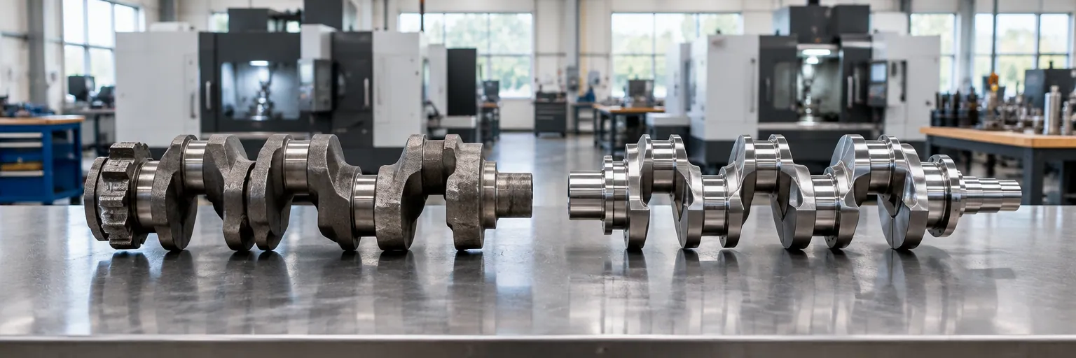
Forging is a bulk forming process that shapes metal by compressive force between dies, either hot or cold, using a mechanical, hydraulic or screw press, or a drop hammer. Open-die forging works metal between flat or simple dies, cold forging and heading form small parts and bolts without heat, and impression-die forging squeezes metal into a closed cavity, leaving flash that must be trimmed. Because the metal flows to fill the tooling, deformation refines the grain structure and aligns it with the outer contour of the part.
Machining is a subtractive process that cuts away unwanted material from a solid block, bar or blank using milling cutters, lathe turning tools or drills. When you machine a part directly from bar stock, the cutting tool slices across the bar's unidirectional grain lines rather than bending them around corners and fillets.
The two processes also sit at opposite ends of the precision scale. Hot forging leaves oxide scale, a decarburized skin on steel, a visible parting line and wide dimensional tolerances. Machining is the reference process for precision, holding tight tolerances and smooth finishes directly from the cutting tool.
Strength, grain flow and material choices
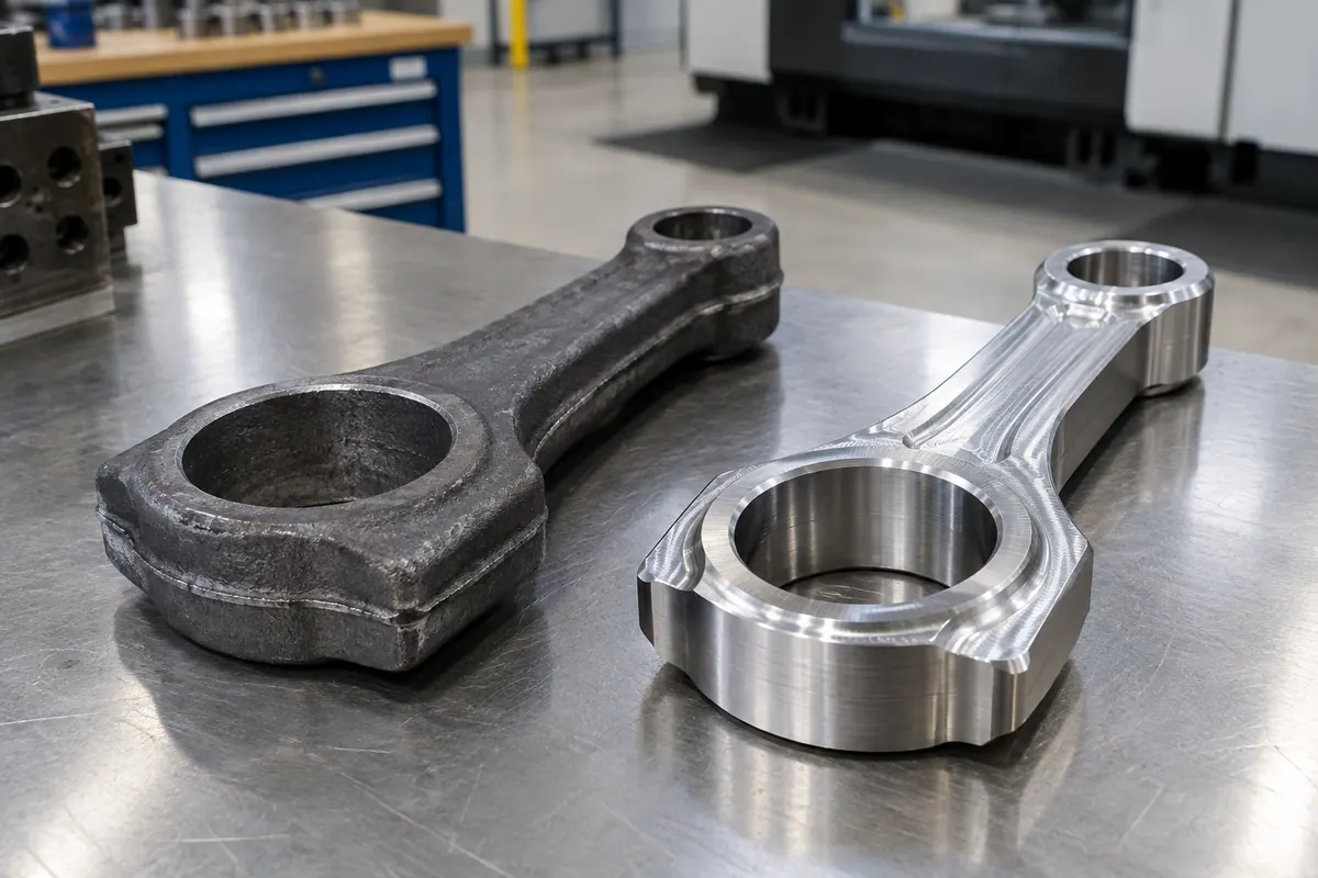
When a part carries high or cyclic loads and must not fail, forging beats machining from solid. Aligning the grain flow along the part gives better strength, toughness and fatigue resistance in the loaded direction than cutting across the grain of a bar or casting the alloy to shape. This is why crankshafts, connecting rods, gears, aircraft structural fittings, hand tools, fasteners and valve bodies are forged.
Not every alloy can be forged, and mechanical properties depend on post-forging heat treatment rather than the nominal alloy on paper:
- Medium-carbon steel, alloy steel, nickel-chromium-molybdenum steel and aluminum are rated excellent for forging; alloy steel forgings are subsequently heat treated to reach their target strength.
- Alpha-beta titanium and austenitic stainless steel are rated good. Titanium must be forged hot within a narrow temperature window to avoid internal cracks, while austenitic stainless requires high temperatures and higher forces than carbon steel.
- Nickel superalloys are rated fair because their high-temperature strength demands high forces and tight temperature control.
- Brittle materials such as gray cast iron, ceramics and glass are unsuitable for forging and will crack under deformation.
Machining works on almost any metal bought as bar or plate stock, as well as plastics and composites. However, compressible materials like foam cannot hold guaranteed tolerances when machined, and clear plastics come off the tool with matte or swirled faces.
When to choose each process by volume and geometry
Quantity and tooling cost usually set the boundary between the two routes:
- Choose machining from solid for one to a few hundred pieces. Machining needs no dedicated die, so you pay mainly for material removed and cutting time. It is best for prismatic and rotational shapes where most of the starting bar remains in the finished part.
- Choose impression-die forging when quantities run from the hundreds into the millions. Closed dies are expensive to sink and wear out over time, so you need production volume to amortize the tooling cost.
- Choose open-die forging when you need a single large shaft or ring with worked grain structure and cannot justify a closed die.
Watch the material removal ratio when evaluating machining. Because machining cost scales with chip volume and the number of setups, a part that turns most of a solid billet into chips, or requires many re-clampings, is a candidate for a near-net forged or cast blank.
Combining both: machining a forged blank
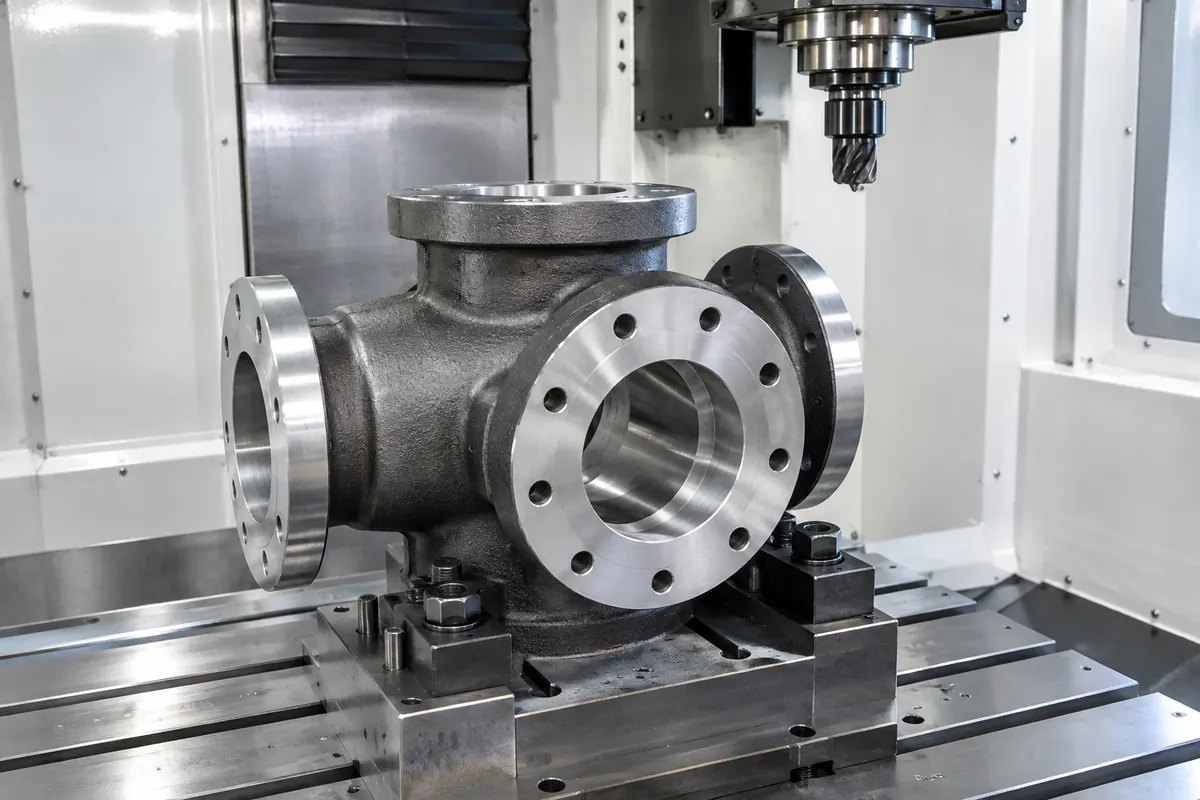
You rarely have to choose strictly one or the other for production hardware. Because hot forgings leave the die with surface scale, trimmed flash and coarse tolerances, most closed-die forgings are finish-machined on their functional features.
Use the forging to establish the main structural envelope, ribs and webs with continuous grain flow. Then set up the forged blank in a mill or lathe to cut mating faces, precision bores and threads.
When designing a forged part that will be machined, follow three practical rules:
- Add machining stock to every surface of the forging that needs a tolerance or finish the die cannot hold.
- Specify clearly on the 2D drawing which surfaces are left as-forged and which are machined, and call out post-forging heat treatment separately.
- Plan a rough machining pass before the finishing pass. Residual stresses locked in during forging and flash trimming can make the part move as skin material is cut away; roughing first lets the part relax before you cut final tolerances.
Design rules for forged vs machined features
If you design for impression-die forging, you design for metal flow and die release. No universal numerical limits apply across all shops, so ask your forge for its draft and tolerance practice for your alloy and part size. Apply these core geometry rules:
- Put draft on every surface parallel to the die motion so the part releases from the cavity.
- Place the parting line on a single plane and at the largest cross-section where possible.
- Use generous fillet and corner radii so metal flows smoothly into ribs without causing die cracks, laps, cold shuts or underfill.
- Keep webs and ribs thick enough for the hot metal to fill before chilling.
If you design for CNC machining from solid or for the machined features on a forging, you design around rotating cutters and workholding:
- Keep pocket depths within 4 times the cutter diameter and internal corner radii at least 1/3 of the pocket depth.
- Keep metal walls at least 0.8 mm (0.031 in) thick.
- Size holes to standard drills, keep hole depth within 4 diameters, and keep unsupported bar overhang in a lathe chuck or collet to at most 3 times the workpiece diameter.
- Prefer threads of M6 or larger (minimum possible is M1) so the shop can use CNC threading tools instead of taps that risk breaking, and keep thread engagement between 1.5 and 3 times the nominal diameter.
Tolerances, fits and drawing callouts
Forging tolerances are coarse and depend on die wear, part size and alloy, so confirm achievable numbers directly with the forge. On machined surfaces, one manufacturing service publishes a standard capability of ±0.125 mm (0.005 in) and ±0.025 mm (0.001 in) on request, with an as-machined surface roughness around 3.2 µm Ra. Another service defaults to ±0.005 in (0.127 mm) on metal features of size and location and 0.005 in (0.127 mm) on flatness and form over 0 to 12 in (0 to 305 mm). Treat these figures as vendor guidelines rather than universal rules, and confirm what your shop holds.
To control general tolerances on machined features without cluttering the drawing, call out ISO 2768-1 in the title block with a tolerance class such as f (fine) or m (medium). The standard sets permissible plus-or-minus deviations by nominal size range: for example, a dimension over 30 up to 120 mm allows ±0.15 mm (0.006 in) in class f and ±0.3 mm (0.012 in) in class m. On traditional U.S. inch drawings without explicit tolerances, shop practice expects ±0.005 in (0.127 mm) on three-decimal dimensions, ±0.010 in (0.254 mm) on two-decimal dimensions, and ±1/64 in (0.015625 in or 0.397 mm) on fractions.
For precision machined shafts and bores, call out ISO 286-2 tolerance classes on the dimension, such as an H7/g6 or H7/h6 clearance fit. Both mating parts must be machined to their respective classes to achieve the fit: for a nominal size over 10 up to 18 mm, an H7 hole is held to 0 to +18 µm and a g6 shaft to -17 to -6 µm, yielding 6 to 35 µm of assembled clearance (an h6 shaft is -11 to 0 µm, giving 0 to 29 µm clearance). Always include a 2D technical drawing alongside STEP or IGES files to carry thread callouts, fit classes and forged-versus-machined surface indications.
Design rules at a glance
| Rule | Value | Note | Source |
|---|---|---|---|
| Typical economical quantity | Impression-die forging: hundreds to millions (open-die: 1+); Machining: 1 to a few hundred | Closed forging dies are expensive and pay back over volume; machining needs no dedicated tooling. | [1] |
| Grain flow and fatigue strength | Forging: aligned with part contour; Machining: cut across bar grain | Forging refines grain by deformation for higher toughness and fatigue resistance under cyclic load. | [1] |
| Material suitability (metals) | Forging: carbon/alloy steels, Al excellent, Ti/stainless good, cast iron unsuitable; Machining: most bar/plate metals | Alpha-beta titanium must be forged hot within a narrow temperature window; brittle materials cannot be forged. | [1] |
| Surface condition as-produced | Forging: oxide scale, decarburized skin, flash, draft; Machining: about 3.2 µm Ra clean cut | Hot forgings require flash trimming and finish machining on mating faces, bores and threads. | [1] |
| Standard linear tolerance (vendor guideline) | Forging: coarse, alloy and size dependent; Machining: ±0.125 mm (±0.005 in) standard, ±0.025 mm (±0.001 in) on request | Published guideline from Hubs and Xometry (±0.005 in / 0.127 mm default for metals); confirm with your shop. | [2] |
| Wall, web and rib thickness | Forging: thick enough for hot metal to fill die; Machining: at least 0.8 mm (0.031 in) in metal | Avoid thin, deep ribs and abrupt section changes in closed-die forgings to prevent underfill. | [2] |
| Internal radii and pockets | Forging: generous fillets/radii to prevent laps and die cracking; Machining: depth up to 4x cutter diameter, corner radius at least 1/3 depth | Proportions guide tool deflection in machining and metal flow in forging. | [2] |
| Thread size and length (machined) | M6 or larger recommended (M1 minimum); length 1.5x to 3x nominal diameter | Threads M6 and up allow CNC threading tools instead of taps; forgings have threads machined after forming. | [2] |
| General machining tolerance (ISO 2768-1, over 30 to 120 mm) | Class f (fine): ±0.15 mm (0.006 in); Class m (medium): ±0.3 mm (0.012 in) | Applies to metal removal dimensions without individual tolerance callouts when ISO 2768-1 is referenced. | [5] |
| Machined clearance fit example (ISO 286-2, over 10 to 18 mm) | H7/g6: 6 to 35 µm clearance; H7/h6: 0 to 29 µm clearance | H7 hole is 0 to +18 µm; g6 shaft is -17 to -6 µm; h6 shaft is -11 to 0 µm. | [6] |
Common questions
- When does a forged part beat one machined from solid bar?
- A forging wins when the part sees high or cyclic loads and must not fail, or when production runs into the hundreds to millions of pieces. Forging deforms the metal so the internal grain follows the part's contour, giving better toughness and fatigue strength than cutting across the grain of a solid bar. At high volumes, near-net forging also avoids the time and waste of hogging large amounts of chips from solid billet.
- Can I get a low-volume part forged without paying for closed dies?
- Yes, if the geometry suits open-die forging. Open-die forging shapes metal between flat or simple dies without a part-specific cavity, making it practical for single large shafts or rings that still need a worked grain structure. You then machine the open-die forging to final dimensions.
- Why do forged blanks warp during CNC machining, and how do I prevent it?
- Hot forging and flash trimming leave residual stresses in the blank. When a machinist cuts away the outer skin on one side, those stresses rebalance and the part can move. To prevent out-of-tolerance finishes, rough machine the forging first so the metal can shift, and then run a light finishing pass to bring critical features into tolerance.
- Do I still need a 2D drawing if I send a 3D STEP model for a machined forging?
- Yes. A STEP or IGES file cannot carry thread specifications, surface roughness requirements, ISO fit classes or notes indicating which surfaces are left as-forged versus finish-machined. You also need the drawing to specify the post-forging heat treatment condition separately from the raw material grade.