Drilling design guide: hole depth, diameters and tolerances
Learn how to design drilled holes for machining, including standard diameters, depth-to-diameter limits, surface finish, and when to ream or bore.
Drilling produces or enlarges round holes using a rotating tool. In CNC milling and turning, it runs as an automated machine cycle, while manual shops use drill presses, lathes, and mills. Because a standard twist drill can wander, clog with chips, and cut slightly oversize, designing parts for drilling means respecting depth limits, giving the tool a square entry, and calling out follow-up operations when tight tolerances matter.
What drilling is and when to use it
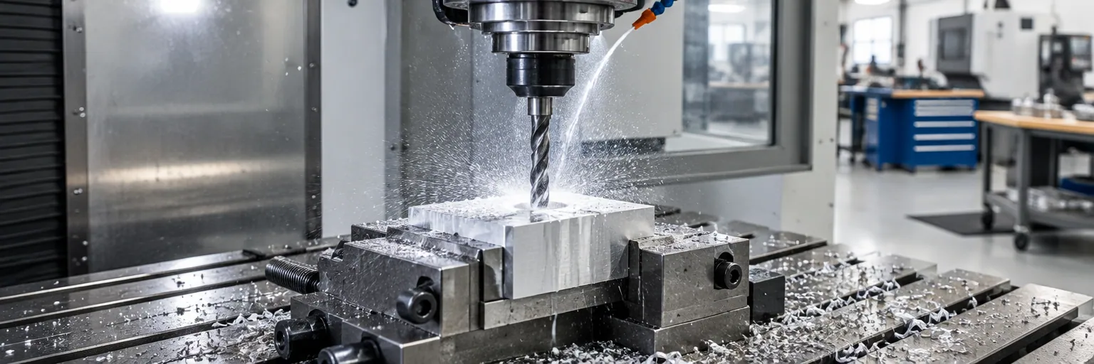
Drilling cuts or enlarges a round hole with a rotating drill bit. On CNC mills and lathes, the operation runs as a programmed drilling cycle. In manual shops, machinists drill on hand-feed or power-feed drill presses, engine lathes with the drill in the tailstock, or milling machines when hole locations must be set accurately with feed-screw graduations.
Use drilling whenever you need a round hole and standard position and diameter accuracy are enough. Threaded holes also begin as drilled holes cut to the required tap drill diameter. When a hole needs a tighter diameter tolerance or a smoother wall than a drill can produce alone, the shop drills the hole slightly undersize and follows up with reaming or boring.
Sizing and designing holes
Published design guidance from manufacturing services such as Hubs recommends using standard drill diameters, keeping hole depth within 4 times the diameter (or up to 10 times with care), and avoiding holes smaller than 2.5 mm (0.098 in) unless you intend to use micro-machining. These figures are a service's published design guidance rather than a hard limit at every shop, so confirm capability with your machinist.
Across standard U.S. tooling, common twist drills range from wire gage No. 80 at 0.0135 in (0.343 mm) up to 3.500 in (88.9 mm). Holes larger than 3.500 in require special tooling rather than twist drills, and standard power-feed drilling machines typically handle twist drills up to 2 in.
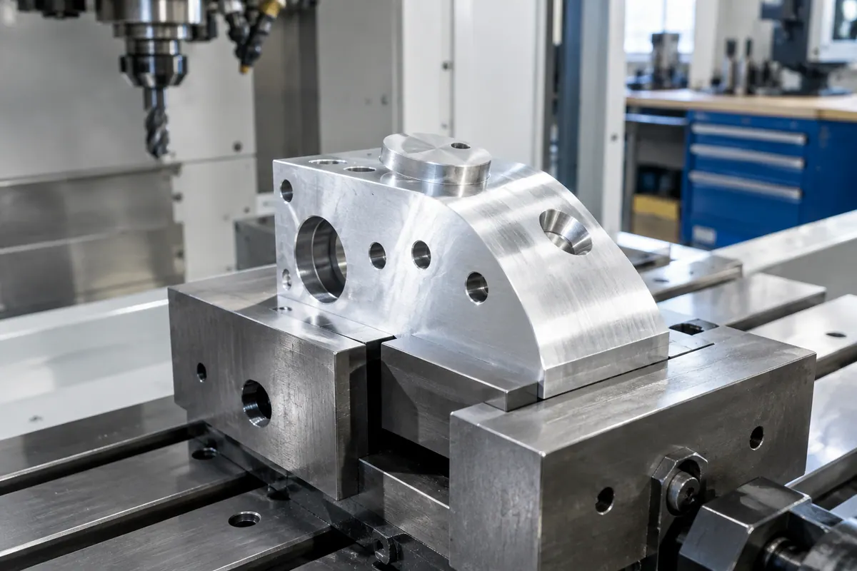
Give the drill a flat, square surface to start on and clear space to break through at the exit. When a hole must start on a rough, cast, or curved surface that is not square to the tool, design a spotface so the cutter can create a flat seat before drilling. Always measure and call out blind hole depth along the cylindrical side wall of the hole, never to the angled cone point at the bottom.
For secondary fastener features, standard machine countersinks for recessed flathead screws use an 82 degree included angle, while lathe center holes use a 60 degree countersink. Other cones at 90, 100, 110, and 120 degrees exist for special needs. If you call out a counterbore, the counterbore tool uses a pilot that needs a sliding fit inside the drilled hole.
Tolerances, oversizing, and surface finish
A drilled hole is always slightly larger than the nominal diameter of the drill. For example, a 1/4 in drill can produce a hole several thousandths of an inch over 1/4 in because of drill point grind, chuck and spindle accuracy, and setup rigidity. In general, a drilled hole is neither perfectly round nor sized to tighter than a few hundredths of a millimeter without a secondary operation.
In ordinary production, the wall of an as-drilled hole without reaming or boring has an average surface roughness between 1.6 and 6.3 um Ra (63 to 250 uin Ra), depending on material, tooling, and machine settings.
On your part drawings, specify the required finished hole diameter and tolerance rather than calling out a specific drill bit or shop method. That lets the machinist decide whether a twist drill alone is sufficient or whether the hole must be center-drilled, pilot-drilled, and reamed or bored. General tolerances from ISO 2768-1 and ISO 2768-2, as well as socket cap screw dimensions from ASME B18.3, apply to typical drilled and counterbored features.
Material selection and machinability
How cleanly a part drills depends heavily on the material family and its heat-treated state. Reference ratings below are general advisory guides for choosing a material and process route, not the guaranteed capability of a specific shop:
- Aluminum and magnesium: Rated excellent. Aluminum drills fast with sharp, polished-flute bits and frequent chip clearing. Magnesium requires low force, though its chips and dust present a fire hazard.
- Gray cast iron and brass: Rated excellent. Gray cast iron produces short chips that clear easily dry or with coolant. Brass drills cleanly when the drill rake angle is reduced to prevent grabbing.
- Low- and medium-carbon steels: Rated good. Low-carbon steel drills readily with high-speed steel (HSS) or carbide and coolant; medium-carbon steel drills well in the normalized state.
- Precipitation-hardening stainless steel: Rated good when drilled in the solution-treated condition.
- High-carbon steel, austenitic stainless steel, and pure copper: Rated fair. High-carbon steel should be drilled in the annealed state, or with carbide if already hardened. Austenitic stainless steel work-hardens rapidly, requiring stiff cobalt HSS or carbide bits, coolant, and a steady feed without dwelling. Pure copper is gummy and tends to grab at breakthrough.
- Titanium and nickel superalloys: Rated poor. Alpha-beta titanium concentrates heat at the tool tip, while nickel superalloys work-harden severely. Both need sharp bits, low cutting speeds, firm feeds, and heavy coolant.
- Plastics: ABS, polycarbonate (PC), and polyamide (nylon) are rated good, while polyethylene is rated fair. Polyethylene needs a slow-spiral bit and low speed to prevent melting, PC needs low speed and coolant to avoid stress cracking, and polyamide hole sizes will shift as the material absorbs moisture.
How shops set up and run drilling jobs
Understanding shop practice helps you see why certain features add setup time or tooling cost. Standard general-purpose twist drills are ground to a 118 degree included point angle (59 degrees per lip) with 8 to 12 degrees of lip clearance and a common helix rake angle of 30 degrees (within an 18 to 45 degree range). For very hard materials like armor plate, or soft grabbing metals like brass and bronze, machinists reduce the rake angle to support the cutting edge and stop the bit from hogging in.
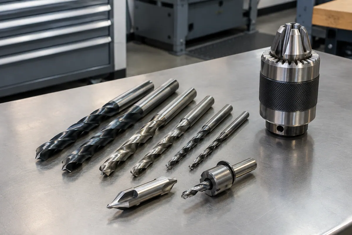
To start a hole accurately, shops spot the location with a center drill, cutting no deeper than two thirds of the center drill's tapered cone. Before running a large drill, they drill a pilot hole just wider than the large drill's central web to relieve chisel-edge drag; making a pilot hole too wide lets the outer lips grab and cut out of round.
Machinists calculate spindle speed from published cutting speeds using RPM = (CS x 4) / D for inch units (or RPM = (CS x 320) / D in metric), generally choosing the slower end of the recommended range to account for setup rigidity. With HSS twist drills, typical cutting speeds are 200 to 300 sfm in aluminum, brass, and bronze; 100 to 150 sfm in soft cast iron; 80 to 110 sfm in mild steel; and 70 to 150 sfm in high-tensile bronze. Carbon-steel drills run at roughly half of HSS speeds, while carbide drills run 200 to 300 percent faster.
Feed rate increases with drill diameter. Drills 1/2 in and smaller can be hand-fed on high-speed drill presses (which do not run below 450 rpm), whereas drills over 1/2 in require power-feed machines capable of 50 to 1,800 rpm. Once a hole goes deeper than 4 diameters, the drill must be withdrawn frequently (peck drilling) to clear chips from the flutes.
What to watch out for
Avoid these common pitfalls when designing parts with drilled holes:
- Deep, narrow holes: Beyond 4 diameters deep, flutes clog with chips, causing the drill to drag, wander, and cut oversize. Small drills under 2.5 mm (0.098 in) clog fastest and break easily.
- Unsupported thin sheet: Breakthrough upthrust bends thin workpieces and snags the drill flutes. Shops must back thin sheet with wood or metal, or switch to a low-helix, zero-rake sheet metal drill.
- Unclamped or round parts: Workpieces must never be held by hand; shops clamp flat parts to the table or hold round shafts and pipes in V-blocks so the drill cannot grab at breakthrough.
- Interrupted or angled entries: Starting a drill on a sloped or rough surface deflects the tip and can snap the tool or counterbore pilot unless a flat spotface is machined first.
- Dwelling in work-hardening alloys: Letting a drill rub without cutting in austenitic stainless steel or nickel superalloys hardens the bottom of the hole, dulls the tool, and splits the drill.
Design rules at a glance
| Rule | Value | Note | Source |
|---|---|---|---|
| Common twist drill diameter range | 0.0135 to 3.500 in (0.343 to 88.9 mm) | Wire gage No. 80 to largest common twist drill; power-feed presses in manual handle up to 2 in. | [2] |
| Recommended minimum hole diameter | 2.5 mm (0.098 in) | Vendor design guideline (Hubs); smaller holes require micro-machining. | [1] |
| Recommended maximum depth-to-diameter ratio | 4:1 typical (up to 10:1 with care) | Vendor design guideline (Hubs); holes deeper than 4xD require frequent chip clearing. | [1] |
| As-drilled surface roughness (Ra) | 1.6 to 6.3 um (63 to 250 uin) | Average production range for drilled hole walls without reaming or boring. | [3] |
| General-purpose drill point angle | 118 degrees included (59 degrees per lip) | Both lips must be equal in angle and length to prevent oversized holes. | [2] |
| General-purpose drill lip clearance | 8 to 12 degrees | Chisel edge sits at about 45 degrees to the cutting edges when ground properly. | [2] |
| Drill helix rake angle | 18 to 45 degrees (30 degrees most common) | Reduce rake for very hard materials (armor plate) and soft grabbing metals (brass, bronze). | [2] |
| Standard countersink angles | 82 degrees (flathead screws); 60 degrees (lathe centers) | 90, 100, 110, and 120 degree cones are used for special applications. | [2] |
| Counterboring hand-feed rate | 0.002 to 0.005 in/rev (0.05 to 0.13 mm/rev) | For standard counterbore cutters on a drilling machine; adjust for metal and tool condition. | [2] |
| Cutting speed in aluminum, brass, and bronze (HSS) | 200 to 300 sfm | Carbide runs 200% to 300% faster; carbon-steel drills run at about half speed. | [1] |
| Cutting speed in mild steel (HSS) | 80 to 110 sfm | Use cutting fluid freely to carry away heat and wash out chips. | [1] |
| Cutting speed in soft cast iron (HSS) | 100 to 150 sfm | Gray cast iron drills dry or with coolant and forms short, easy-to-clear chips. | [2] |
Common questions
- Why do drilled holes come out slightly larger than the drill bit diameter?
- Every drilled hole cuts slightly oversize, often by several thousandths of an inch on a 1/4 in drill, because of minor variations in drill point grinding, chuck and spindle runout, and the rigidity of the machine and workpiece setup. If you need an exact diameter or a tolerance tighter than a few hundredths of a millimeter, specify the finished tolerance on the drawing so the shop can drill undersize and ream or bore to finish.
- How deep can a hole be drilled without special tooling?
- A good design target is to keep hole depth within 4 times the drill diameter, and no more than 10 times the diameter when done with extra care. Once a hole goes past 4 diameters deep, chips pack into the flutes and cause the drill to drag, overheat, and wander off center, requiring frequent peck cycles to clear the hole.
- How is blind hole depth measured on a machine drawing?
- Always measure and dimension blind hole depth along the straight cylindrical side wall of the hole, never to the bottom of the angled cone left by the drill point.
- When does a hole need a pilot drill or a center drill?
- Shops use a stiff center drill first whenever hole position must be aligned accurately, cutting no deeper than two thirds of the tool's tapered section. For large holes or on low-power machines, they follow with a pilot drill slightly wider than the large drill's central web so the chisel edge does not scrape and overload the spindle.
- How should I design holes in thin sheet metal or copper?
- Thin sheet metal and gummy materials like pure copper tend to grab the drill flutes and bend upward as the tool breaks through. In the shop, machinists back thin workpieces with wood or metal support blocks or switch to low-helix, zero-rake sheet metal drills. Designing flat clamping surfaces around the hole exit makes it much easier for the shop to support the part from below.