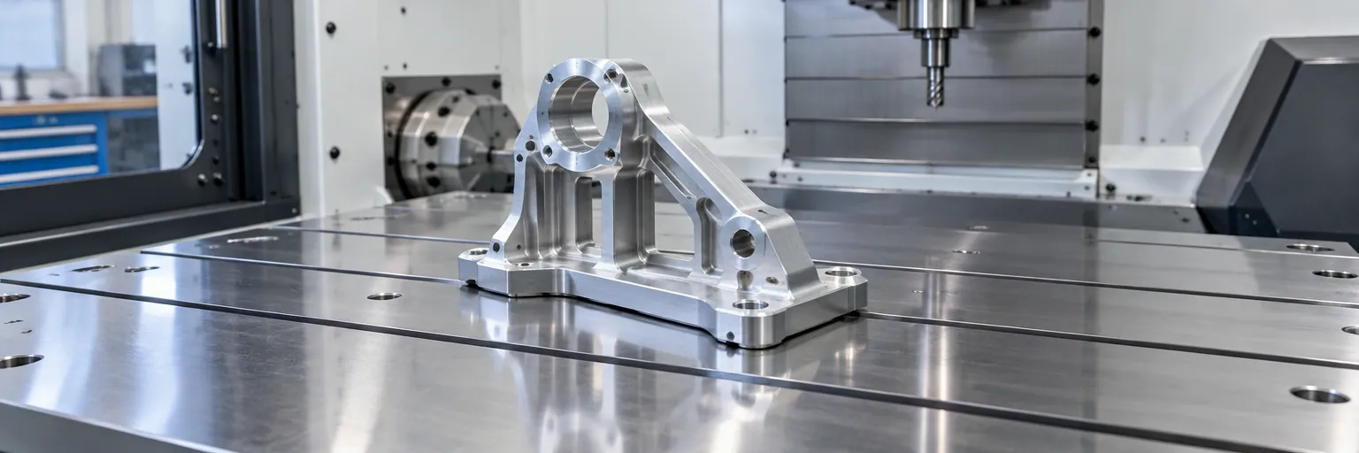
CNC machining design guide: milling, turning, rules and tolerances
Learn when to use CNC milling and turning, with practical design rules for pockets, corners, walls, holes, threads, tolerances, and surface finish.
CNC machining cuts material away from solid stock, bar, or castings to produce precise parts. It is the go-to process when you need tight tolerances, engineering materials bought as stock, or volumes from a single prototype to a few hundred pieces. Because machining costs scale with machine time and setups, designing around tool geometry keeps your parts buildable and affordable.
What CNC machining is and when to use it
Machining is a subtractive process where rotating tools or workpieces remove material until your desired geometry remains. It is the reference process for precision and surface quality. It fits best when your part requires stock metals or plastics rather than cast or printed materials, and when quantities do not justify hard tooling, typically from one to a few hundred parts (or up to thousands in general milling service).
Machining suits prismatic shapes and bodies of revolution. Cost scales directly with the volume of material removed and the time the cutter spends in the cut. If your design is mostly empty space or needs to be re-clamped many times to reach every face, redesigning the part or choosing another process will save money.
CNC milling vs CNC turning
Machining divides by how the cutting tool and the workpiece move.
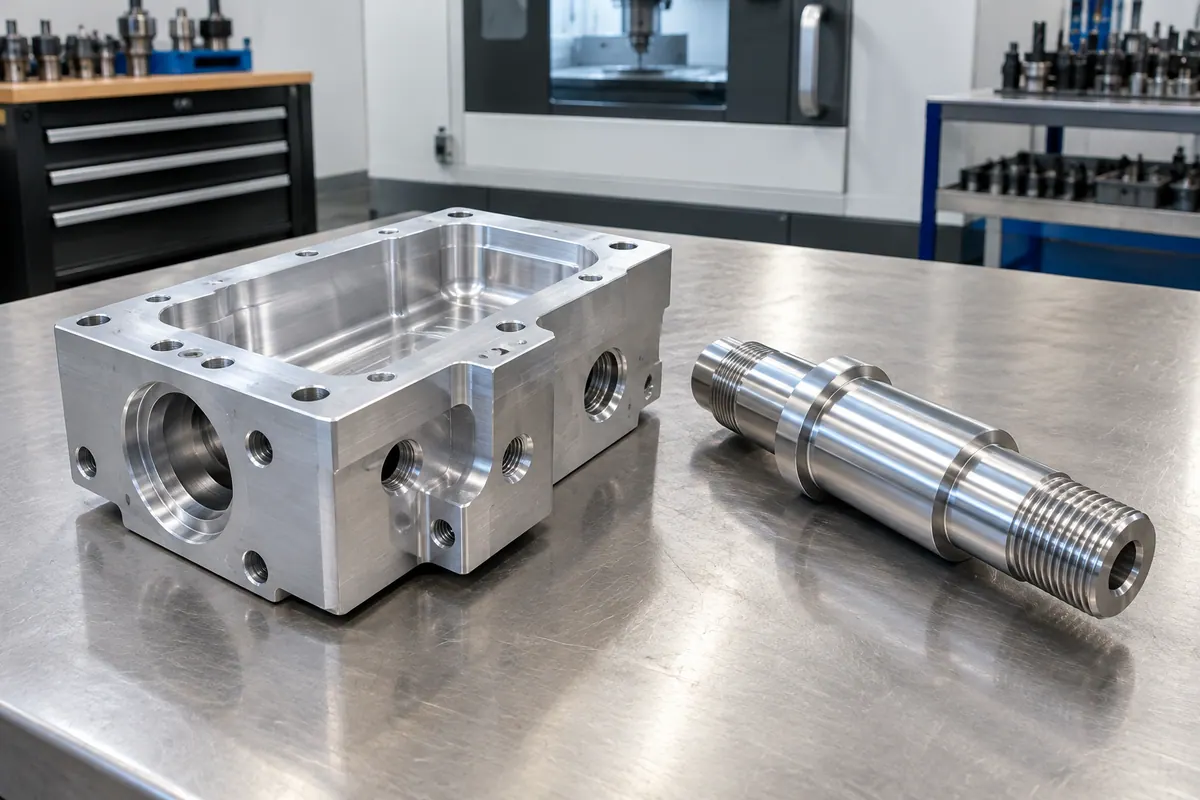
- CNC milling rotates a multi-edge cutter and moves it across a stationary workpiece along programmed toolpaths. Three-axis mills cut everything visible from above in one setup. Indexed (three-plus-two) or simultaneous five-axis mills add two rotary axes to reach multiple faces and compound surfaces without re-fixturing. Milling is the default choice for brackets, housings, manifolds, fixtures, and plates up to a typical envelope of about 400 mm (15.7 in) in the longest dimension.
- CNC turning spins the workpiece in a lathe chuck or collet against a stationary or driven cutting tool. It is faster and more concentric than milling for shafts, pins, bushings, and round features, and bar stock can feed automatically for higher quantities. Modern turning centers include driven tools and a second spindle to add flats, cross-holes, and back-side features in one operation.
When a round part also has prismatic features, using a lathe with driven tools or a turn-then-mill sequence is more efficient than milling the entire part from a block.
Design rules for pockets, corners, walls, and Part rigidity
Cutting tools are cylindrical, have finite reach, and deflect under side loads. The numbers below come from published service design guides (such as Hubs) and trade references; treat them as practical starting points and confirm exact limits with your shop.
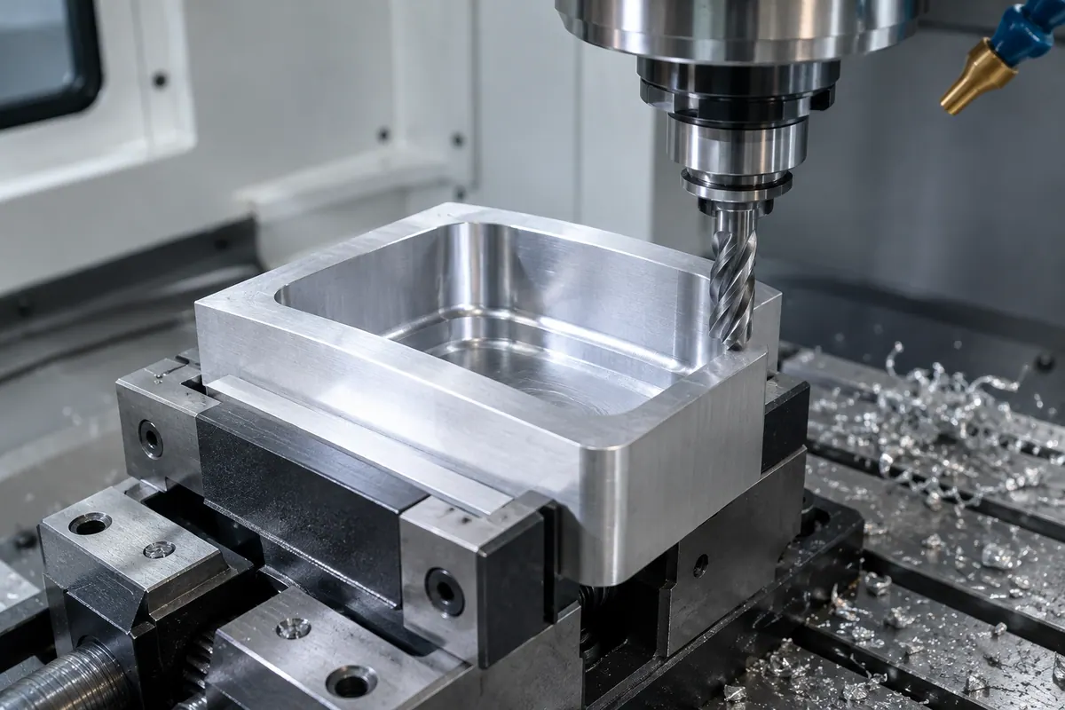
- Pocket depth: Keep pocket depth within 4 times the cutter diameter to prevent tool deflection and chatter. Depths up to 10 times the cutter diameter are feasible with special tooling.
- Internal corner radii: A rotating end mill cannot cut a sharp internal vertical corner. Make internal vertical radii at least one-third of the pocket depth, and slightly larger than the radius of the cutter so the tool does not stall in the corner.
- Wall thickness: Keep metal walls at 0.8 mm (0.031 in) or thicker so they do not vibrate or deform under cutting forces.
- Minimum feature size: Keep general milled features no smaller than 2.5 mm (0.098 in).
- Turning rigidity and workholding: On a lathe, keep length-to-diameter ratios modest. Work held in a chuck or collet should not overhang by more than 3 times the workpiece diameter without adding a tailstock center or steady rest. If a turned part needs tailstock support, design a 60 degree center hole drilled to about two-thirds (0.6667) of the center drill body diameter. Avoid thin-walled tubes that can distort in the chuck, and design diameters to be cut in a single chucking so you do not pay for setup concentricity tolerances.
Design rules for holes and threads
Drills and threading tools work best when sized to standard tooling and modest depths.
- Hole size and depth: Specify standard drill sizes and keep hole depth within 4 times the diameter.
- Thread size: While threads down to M1 (1 mm nominal diameter) can be cut, design threads at M6 (6 mm) or larger whenever possible. From M6 upward, shops can use CNC threading tools instead of taps, which machinists prefer because it avoids the risk of breaking a tap in your part.
- Thread engagement length: Keep thread length between 1.5 and 3 times the nominal diameter. The first 1.5 diameters of thread carry most of the load, so threading deeper than 3 diameters adds machining time and risk without adding strength.
- Modeling and drawings: If you model internal threads as pilot holes in CAD, size the pilot hole to approximately 75% (0.75) of the nominal thread diameter. Always include a 2D technical drawing to call out thread specifications, because STEP and IGES files cannot carry thread data.
Tolerances, fits, and surface finish
A tolerance or surface finish is a request on your drawing, not an automatic property of machining. Every tightened tolerance requires slower finishing passes and manual inspection, so put tight tolerances only on features that mate with other parts.
- Service default tolerances: Published service guides vary slightly. For example, Hubs states ±0.125 mm (±0.005 in) as standard and ±0.025 mm (±0.001 in) on request for specific features. Xometry states a default of ±0.005 in (±0.127 mm) for metal features of size and location and ±0.010 in (±0.254 mm) for plastics and composites. On traditional inch drawings with no block tolerance, shops typically hold ±0.005 in (0.127 mm) on three-decimal dimensions, ±0.010 in (0.254 mm) on two-decimal dimensions, and ±1/64 in (0.015625 in or 0.397 mm) on fractional dimensions.
- General tolerances (ISO 2768-1): Many metric drawings call out ISO 2768-1 in the title block (for example, 'ISO 2768-m' for medium or 'ISO 2768-f' for fine) to cover all dimensions without individual tolerances. The permissible deviation scales with feature size: for a dimension over 6 up to 30 mm, class m allows ±0.2 mm and class f allows ±0.1 mm; for a dimension over 120 up to 400 mm, class m allows ±0.5 mm and class f allows ±0.2 mm.
- Form and orientation tolerances: In Xometry's published standards for metals, flatness, parallelism, perpendicularity, cylindricity, circularity, concentricity, and straightness default to 0.005 in (0.127 mm) with 0.5 degree angularity over a 0 to 12 in part length, rising to 0.010 in (0.254 mm) over 12 to 24 in, and 0.016 in (0.397 mm) with 1 degree angularity over 24 to 36 in. Plastics and composites typically hold double the metal form tolerance.
- Hole and shaft fits (ISO 286-2): For precise mating diameters, call out ISO 286 hole-basis fit codes on your drawing rather than inventing arbitrary limits. For example, on a nominal size over 10 up to 18 mm, calling out an H7/g6 sliding clearance fit makes the H7 hole 0 to +18 µm and the g6 shaft -17 to -6 µm, giving 6 to 35 µm of assembled clearance. Calling out an H7/k6 transition fit on the same 10 to 18 mm size keeps the H7 hole at 0 to +18 µm and sets the k6 shaft to +1 to +12 µm, giving between 17 µm of clearance and 12 µm of interference.
- Surface finish: As-machined surfaces typically measure about 3.2 µm Ra. You can request finer finishes of 0.8 µm Ra or 0.4 µm Ra on critical faces at an added cost.
Material selection and machinability
The material you specify changes cutting speeds, tool wear, and achievable appearance.
- Excellent machinability: Aluminum is the reference material for CNC milling, allowing high cutting speeds, light forces, and long tool life. Free-machining brass is the fastest-machining common metal (the 100 point on the machinability scale), and gray cast iron machines excellently because its graphite flakes break the chip.
- Good machinability: Low-carbon steel (such as cold-drawn 1018 to avoid gummy chips), medium-carbon steel (especially normalized), chromium-molybdenum steel, ductile cast iron, bronze, and beryllium copper (which requires dust and fume control due to toxicity) all machine well. Precipitation-hardening stainless steel machines well in condition A before aging.
- Fair to poor machinability: Austenitic stainless steel work-hardens under the tool and conducts heat poorly, requiring rigid setups, sharp tools, and positive feeds; grade 303 is the free-machining option. Duplex stainless steel is harder and tougher than 304 and requires slower speeds. High-carbon steel and high-speed steel are machined in the annealed state and ground after hardening. Commercially pure titanium concentrates heat at the cutting edge, requiring low speed, high feed, and flood coolant. Pure copper is soft and gummy, tearing rather than cutting cleanly, so choose brass when machinability matters.
- Plastics and foam: Clear or transparent plastics will have matte faces or translucent swirl marks as-machined, and a frosted look if bead blasted. Do not expect guaranteed tolerances on foam or similar compressible materials.
Design rules at a glance
| Rule | Value | Note | Source |
|---|---|---|---|
| Maximum pocket depth | 4x cutter diameter (up to 10x with special tooling) | Published service guideline to prevent tool deflection | [1] |
| Minimum internal vertical corner radius | 1/3 of pocket depth (and slightly larger than cutter radius) | Allows the rotating end mill to turn without stalling | [1] |
| Minimum wall thickness (metals) | 0.8 mm (0.031 in) | Published service guideline to prevent chatter and distortion | [1] |
| Minimum general feature size (milling) | 2.5 mm (0.098 in) | Published service guideline for CNC milling | [1] |
| Maximum hole depth | 4x hole diameter | Use with standard drill sizes | [1] |
| Recommended minimum thread size | M6 (6 mm) or larger (M1 absolute minimum) | Allows CNC threading tools instead of fragile taps | [1] |
| Recommended thread length | 1.5x to 3x nominal thread diameter | Longer threads add no strength | [1] |
| Threaded pilot hole diameter in CAD | 75% (0.75) of nominal thread diameter | Always accompany with a 2D drawing calling out the thread | [3] |
| Maximum unsupported lathe overhang | 3x workpiece diameter | Beyond this, support the work with a tailstock center or steady rest | [2] |
| Typical milling part envelope | Up to 400 mm (15.7 in) in longest dimension | General service CNC milling | [1] |
| Standard linear tolerance (service defaults) | ±0.125 mm / ±0.005 in (metals); ±0.010 in / ±0.254 mm (plastics) | Published defaults from Hubs and Xometry; confirm with your shop | [1] |
| Tight feature tolerance (on request) | ±0.025 mm (±0.001 in) | Published service guideline; apply only where mating parts require it | [1] |
| As-machined surface finish | 3.2 µm Ra standard (0.8 µm and 0.4 µm Ra on request) | Finer finishes increase machining time and cost | [1] |
Common questions
- Why should I add a 2D drawing if I am already uploading a 3D STEP file?
- STEP and IGES files only carry 3D geometry. They cannot communicate thread specifications, custom tolerances, ISO 286 shaft/hole fits, or surface finish requirements (such as 0.8 µm Ra on a sealing face). Always include a 2D drawing whenever your part has threads, tight tolerances, or specific finish callouts.
- Why do machinists prefer M6 or larger threads over smaller tapped holes?
- Threads M6 and larger can be cut with rigid CNC threading tools (thread mills) rather than taps. Smaller threads usually require cutting taps, which carry a higher risk of breaking inside the hole and scrapping the part.
- How deep should I make a threaded hole?
- Design thread engagement between 1.5 and 3 times the nominal thread diameter. The first 1.5 diameters carry the majority of the load; going deeper than 3 diameters increases cycle time and tool breakage risk without making the joint stronger.
- What happens if I leave sharp internal vertical corners in my 3D model?
- A rotating cylindrical end mill cannot cut a sharp 90 degree internal vertical corner; it always leaves a radius equal to or larger than the cutter radius. Give internal vertical corners a radius of at least one-third of the pocket depth, and size the radius slightly larger than a standard cutter radius so the tool can follow a smooth path without chattering.
- Can I get optically clear surfaces by CNC machining transparent plastic?
- No. As-machined faces on clear or transparent plastics come off the machine matte or with translucent swirl marks from the cutter, and bead blasting turns them frosted.