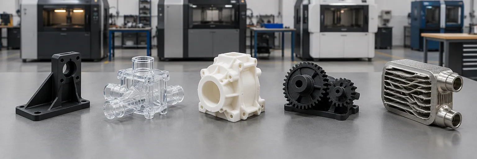
3D printing comparison: FDM vs SLA vs SLS vs MJF vs metal PBF
Compare FDM, SLA, SLS, MJF, and metal powder bed fusion across materials, tolerances, surface finish, strength, and cost to pick the right 3D printing process.
Choosing a 3D printing process comes down to whether your part is a visual model, a precision fit test, a functional polymer production run, or a structural metal component. Each technology builds parts differently, trading off material strength, dimensional accuracy, surface finish, and support requirements. This guide compares fused deposition modeling (FDM), stereolithography (SLA), selective laser sintering (SLS), Multi Jet Fusion (MJF), and metal powder bed fusion (DMLS and SLM) so you can match your design to the right machine.
How the five processes differ
The five main processes fall into three additive families: material extrusion, vat photopolymerization, and powder bed fusion.
- Fused deposition modeling (FDM), also called fused filament fabrication (FFF), pushes thermoplastic filament through a heated round nozzle and compresses each layer onto the one below. Overhangs steeper than 45 degrees from vertical need printed supports.
- Stereolithography (SLA) uses an ultraviolet laser with a 30 to 140 micron spot to trace and cure thin slices in a tank of liquid photopolymer resin. Supports are printed with the part, removed by hand after solvent washing, and the part is post-cured in an ultraviolet chamber.
- Selective laser sintering (SLS) uses a laser to fuse thin layers of heated polymer powder. Because the surrounding unsintered powder supports every layer, no support structures are needed.
- Multi Jet Fusion (MJF) is a polymer powder bed process where an inkjet array jets a fusing agent onto the part area and a detailing agent around the edges before heating elements fuse the layer. Like SLS, the powder bed supports the part so no printed supports are required.
- Direct metal laser sintering (DMLS) and selective laser melting (SLM) use a high-power laser in an inert, heated chamber to fuse or melt metal powder. For design purposes, DMLS and SLM are treated as the same process. Unlike polymer powder beds, metal parts must always be anchored to the base plate with welded metal supports to counter high thermal stress and warping.
Materials and mechanical strength
Your material and loading requirements narrow the choice quickly.
FDM prints real thermoplastics, including PLA, ABS, nylon (PA), and flexible TPU. PLA prints easily with good visual quality but has low impact strength. ABS is stronger but prone to base-layer warping as it cools. Nylon offers high strength and wear and chemical resistance, though it absorbs humidity. Because FDM lays down round-ended beads, the joints between layers form small valleys that concentrate stress. That makes FDM parts anisotropic and weaker across the layers than along them.
SLA cures thermoset photopolymers, including specialty castable resins for investment casting patterns. Because the layers bond chemically during printing, SLA parts are isotropic and orientation does not change their mechanical properties. However, standard SLA resins only imitate engineering plastics. They are generally brittle, prone to creep, and degrade in ultraviolet light and humidity, making them unsuitable for functional loaded parts.
SLS and MJF print functional thermoplastics, primarily nylon (polyamide), TPU, and polypropylene. SLS also runs glass-, mineral-, and carbon-filled nylons, while MJF offers a full-color nylon grade and produces consistent, isotropic mechanical properties. Both processes yield strong, durable parts suited for end-use loads, snap-fits, and living hinges.
DMLS and SLM print structural metals, including austenitic stainless steel (316L), precipitation-hardening stainless steel (17-4 PH), titanium (Ti-6Al-4V), nickel superalloys (Inconel 718), casting-grade aluminum alloys, cold-work tool steels, and pure copper (which is fair to print due to reflectivity and conductivity). Final metal parts are near fully dense, with internal porosity below 0.2 to 0.5 percent. Tensile strength is comparable to wrought metal, though fatigue strength is generally lower due to surface roughness and trace porosity.
Accuracy, feature resolution, and surface finish
Published tolerances and minimum feature sizes come from individual manufacturing services and vary by machine, material, and geometry. Always confirm critical dimensions with your shop.
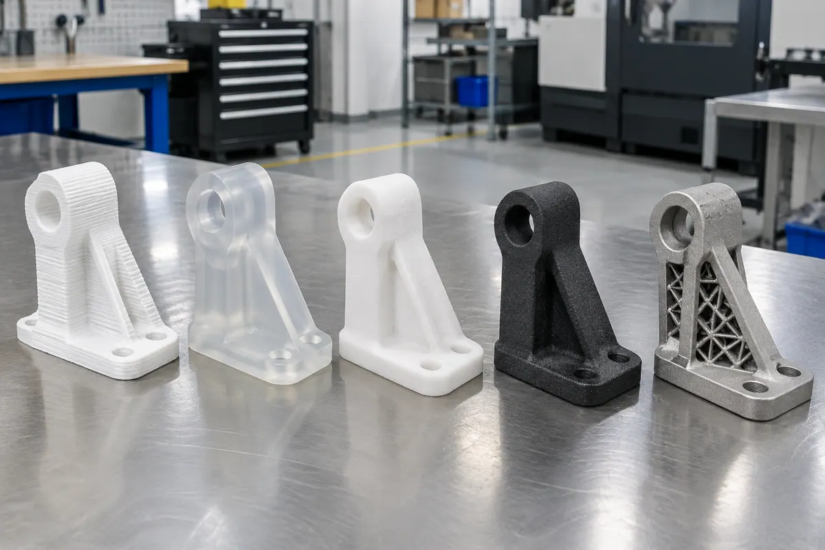
SLA holds the tightest tolerances and finest details of the five processes. One service publishes dimensional tolerances of ±0.002 in (0.051 mm) in the X-Y plane and ±0.005 in (0.127 mm) in the Z build direction for the first inch plus 0.1 percent, while another cites ±0.005 to ±0.012 in (0.127 to 0.305 mm) depending on platform. Minimum features reach down to 0.0025 in (0.063 mm) at micro resolution or 0.010 in (0.254 mm) in X-Y at normal resolution. As-printed SLA surfaces are smooth at about 60 to 120 microinches Ra away from support nibs, with layer thicknesses from 25 to 200 microns.
FDM is the least accurate of the five processes and leaves a visible layer texture. Desktop and industrial layers run from 150 to 400 microns, or 0.008 to 0.013 in (0.203 to 0.330 mm) by one service's defaults. That service publishes a minimum positive feature and hole size of 0.04 in (1.016 mm) and an as-printed surface roughness of 250 to 900 microinches Ra (6.35 to 22.86 microns Ra). Vertical holes print undersized because the nozzle compresses the bead, and the first layer flares out into an elephant's foot unless you add a 45 degree chamfer or radius to build-plate edges.
SLS and MJF sit in the middle on tolerances and leave a grainy, satin matte surface. SLS prints in roughly 0.1 mm (100 micron) layers and MJF in 80 micron layers. Depending on the service, published SLS tolerances are ±0.3 mm (0.012 in) plus ±0.05 mm per additional 25 mm, ±0.010 in (0.254 mm) plus 0.1 percent, or ±0.015 in (0.381 mm) for nylon 12. One service holds ±0.012 in (0.305 mm) plus 0.1 percent on MJF, with minimum walls and features of 0.02 in (0.508 mm), which is finer than its 0.03 in (0.762 mm) SLS limit. As-printed roughness is 250 to 520 microinches Ra for SLS and 250 to 560 microinches Ra for MJF; bead blasting is standard, MJF parts are usually dyed black for uniform color, and vapor smoothing can bring black nylon down to 64 to 100 microinches Ra on request.
DMLS and SLM build in 20 to 50 micron layers and hold ±0.1 mm (0.004 in) on a typical machine, or ±0.003 in (0.076 mm) in X-Y and ±0.006 in (0.152 mm) in Z for the first inch plus 0.1 percent at one service. Recommended minimums are 0.4 mm (0.016 in) walls, 0.6 mm (0.024 in) isolated features, and 1.5 mm (0.059 in) holes. As-printed metal surfaces measure 8 to 10 microns Ra (or 200 to 1000 microinches Ra by another publisher); tighter tolerances and smoother mating faces require secondary CNC machining or polishing.
When to choose each for prototypes or production
Match the process to the part's job, volume, and geometry.
- Choose FDM for quick, low-cost prototypes, jigs, fixtures, brackets, and simple enclosures where visible layer lines and modest accuracy are acceptable. For repeat orders that must match in color and layer height, specify a branded industrial filament rather than general-purpose material.
- Choose SLA for high-precision form-and-fit testing, intricate visual models, and investment casting patterns. SLA resin costs more per volume than FDM filament, and heavy support requirements can make complex orientations uneconomical. If a part exceeds a desktop machine's 145 by 145 by 175 mm (5.7 by 5.7 by 6.9 in) envelope or an industrial 29 by 25 by 21 in (736 by 635 by 533 mm) frame, print it in sections and bond them with a 5- to 30-minute epoxy.
- Choose SLS or MJF for functional polymer prototypes and small-series production runs of roughly 1 to 1,000 parts without tooling costs. Because parts need no supports, they nest densely in the powder bed, making both processes more economical than FDM for larger runs of complex parts. Pick MJF when you want isotropic strength and finer 0.02 in (0.508 mm) features within an 11.1 by 14.9 by 14.9 in (282 by 378 by 378 mm) box. Pick SLS when you need glass- or carbon-filled nylon or a larger build envelope up to 700 by 380 by 580 mm (27.6 by 15.0 by 22.8 in). Above roughly 1,000 parts, injection molding typically takes over.
- Choose DMLS or SLM when a metal part's geometry justifies the process. Geometric complexity adds almost nothing to the build cost, making metal powder bed fusion ideal for consolidated assemblies, topology-optimized brackets, internal cooling channels, and lattices. Plain, blocky shapes designed for traditional machining are rarely economical to print in metal.
Key design rules and common traps across processes
Every 3D printing route has geometry traps that cause warping, cracking, or failed builds. Applicable standards include ISO/ASTM 52911-1 for laser powder bed fusion of metals and ISO/ASTM 52911-2 for laser powder bed fusion of polymers.
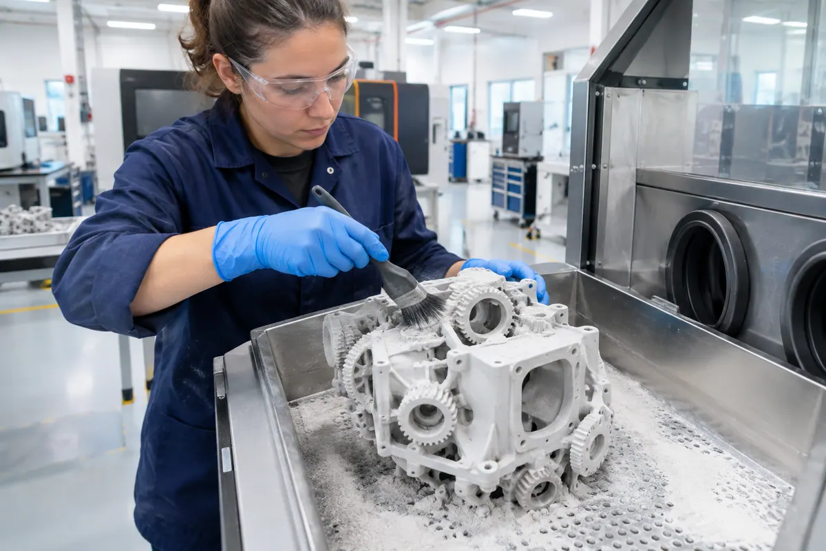
- Hollow parts and drain holes: In SLA, SLS, and MJF, any hollowed section traps liquid resin or loose powder unless you provide escape holes of at least 3.5 mm (0.138 in) diameter. In SLA, trapped uncured resin builds pressure during curing, causing cupping, cracking, or part explosion. For non-functional SLA models, keep hollowed walls at least 2 mm (0.079 in) thick.
- Warping and wall thickness: In SLS and MJF, high process temperatures cause thick or uneven parts to shrink and warp as they cool. Keep walls near a uniform 0.125 in (3.18 mm) and hollow thick sections to a 0.100 to 0.125 in (2.54 to 3.18 mm) shell. For flat or broad polymer parts over 7 in (178 mm), use a filled nylon or a large-frame SLS machine. In DMLS and SLM, keep solid metal sections to 10 mm (0.394 in) or less to prevent thermal distortion and cracking.
- Overhangs and bridges: Keep unsupported FDM overhangs within 45 degrees of vertical and horizontal bridges under 5 mm (0.197 in). In DMLS and SLM, overhangs up to 50 degrees from vertical can print unsupported, and horizontal holes should be shaped like teardrops. In SLA, angle the part to minimize the 2D cross-section peeled from the tank on each layer, keep wide bridges under 21 mm (0.827 in), and face cosmetic surfaces upward away from supports.
- Pins, holes, and threads: Across all five processes, modeled threads rarely work well as printed due to surface roughness or resolution limits; tap holes after printing or install threaded inserts. On FDM, never print threads smaller than M5 (5 mm nominal diameter), keep vertical pins at least 5 mm (0.197 in) in diameter so they receive infill rather than perimeter-only walls, and plan to drill critical vertical holes to size.
Design rules at a glance
| Rule | Value | Note | Source |
|---|---|---|---|
| Process family | FDM: Material extrusion; SLA: Vat photopolymerization; SLS: Polymer powder bed fusion (laser); MJF: Polymer powder bed fusion (inkjet and heat); DMLS/SLM: Metal | Defines how layers are formed and bonded | [1] |
| Standard materials | FDM: ABS, PLA, nylon, TPU; SLA: Thermoset photopolymers, castable resins; SLS: Nylon (unfilled or glass/mineral/carbon-filled), PP, TPU; MJF: Nylon (standard or | SLA resins imitate plastics but are brittle and creep under load | [1] |
| Layer thickness | FDM: 150 to 400 um (0.008 to 0.013 in); SLA: 25 to 200 um (0.001 to 0.004 in); SLS: ~100 um (0.004 in); MJF: 80 um (0.003 in); DMLS/SLM: 20 to 50 um (0.0008 to | Varies by resolution setting and machine class; published service figures | [1] |
| Dimensional tolerance (typical published) | FDM: Least accurate; SLA: ±0.002 in X-Y / ±0.005 in Z (+0.1%/in); SLS: ±0.010 in (+0.1%) or ±0.3 mm; MJF: ±0.012 in (+0.1%) or ±0.25 to ±0.42 mm; DMLS/SLM: ±0.1 | Published service guidelines for well-designed parts; confirm with your shop | [1] |
| Minimum wall thickness | FDM: 0.04 in (1.02 mm) min feature; SLA: 0.4 mm (supported) to 0.6 mm (unsupported), or 0.0025 to 0.010 in; SLS: 0.8 mm (unfilled PA) to 2.0 mm (carbon PA), or | Published service minimums; aluminum in DMLS/SLM requires double the standard feature size at one service | [1] |
| Minimum hole diameter | FDM: 0.04 in (1.02 mm); SLA: 0.5 to 0.8 mm (0.015 to 0.025 in); SLS: 1.5 mm (0.059 in), under 0.04 in may sinter shut; MJF: 0.04 in (1.02 mm); DMLS/SLM: 1.5 mm | Drill critical holes after printing; orient FDM holes vertically | [1] |
| As-printed surface roughness (Ra) | FDM: 250 to 900 uin (6.35 to 22.86 um); SLA: 60 to 120 uin away from supports; SLS: 250 to 520 uin; MJF: 250 to 560 uin; DMLS/SLM: 8 to 10 um (or 200 to 1000 ui | Vapor smoothing brings SLS and MJF black nylon to 64 to 100 uin Ra | [1] |
| Support structures required | FDM: Yes, for overhangs > 45 deg from vertical and bridges > 5 mm; SLA: Yes, removed by hand; SLS: None (powder supports part); MJF: None (powder supports part) | DMLS/SLM parts are stress relieved on the plate before supports are cut | [1] |
| Mechanical isotropy | FDM: Anisotropic (weaker across Z layers); SLA: Isotropic (chemical bond); SLS: Near-isotropic (sintered powder); MJF: Isotropic (uniform thermal fusing); DMLS/ | Orient FDM parts so primary tensile loads run along the layers | [1] |
| Minimum drain hole for hollow parts | FDM: N/A (infill used); SLA: 3.5 mm (0.138 in); SLS: 3.5 mm (0.138 in); MJF: Required for trapped powder (unfused powder stays inside 4 mm shelled full-color pa | At least one hole per hollow cavity; prevents SLA resin cupping and bursting | [1] |
| Typical build envelope (industrial max on file) | FDM: 223 x 223 x 205 mm desktop (larger on Fortus 450/900); SLA: up to 29 x 25 x 21 in (736 x 635 x 533 mm); SLS: up to 700 x 380 x 580 mm (27.6 x 15.0 x 22.8 i | Maximum envelopes depend on resolution and material availability at each service | [1] |
Common questions
- Which 3D printing process holds the tightest tolerances?
- Stereolithography (SLA) holds the tightest tolerances and finest feature details among the polymer processes. One service publishes ±0.002 in (0.051 mm) in the X-Y plane and ±0.005 in (0.127 mm) in the build direction for the first inch, with minimum features down to 0.0025 in (0.063 mm) at micro resolution. However, standard SLA resins are brittle and prone to creep, so use SLA for form-and-fit checks rather than loaded parts.
- Should I choose SLS or MJF for functional nylon production parts?
- Both SLS and MJF print strong, functional nylon parts without support structures and nest parts densely for runs of 1 to 1,000 pieces. Choose MJF when you want isotropic mechanical properties and finer features down to 0.02 in (0.508 mm) within an 11.1 by 14.9 by 14.9 in build box. Choose SLS when you need glass-, mineral-, or carbon-filled nylon, or when your part requires a larger build frame up to 700 by 380 by 580 mm (or 19 by 19 by 17 in at one service).
- Why do metal powder bed fusion (DMLS/SLM) parts need supports when polymer powder bed (SLS/MJF) parts do not?
- In SLS and MJF, the surrounding heated polymer powder supports overhangs so no dedicated support structures are needed. In DMLS and SLM, the high laser temperatures create severe internal thermal stress that warps, distorts, and cracks metal as it cools. Metal supports are welded directly to the base plate to anchor the part during the build and throughout stress-relief heat treatment before the part is cut free.
- Can I 3D print working screw threads directly in my part?
- Across all five processes, printing functional threads is discouraged for small or high-precision fasteners. In FDM, never print threads smaller than M5 (5 mm nominal diameter). In SLS and MJF, rough powder-bed surfaces increase friction and small features can sinter shut. For reliable assemblies in any 3D printing process, tap the hole after printing or install a threaded insert.
- When does metal 3D printing make sense over CNC machining?
- Use DMLS or SLM when geometric complexity earns its keep. Because complexity adds almost nothing to the printing cost, metal powder bed fusion excels at topology-optimized shapes, internal cooling channels, lattices, and consolidated multi-part assemblies. Simple prismatic parts designed for traditional machining are rarely economical to 3D print in metal, and any precision mating faces or tight tolerances tighter than ±0.1 mm (0.004 in) will still require secondary CNC machining.